Figure 7.1 THD Sensor Address: DialCode Settings
NOTE: DIP switch in the ONposition means 1 or 0.
When the Group is 0001 and Num is 00, the temperature and humidity data collected by the sensor is displayed on the LCD
screen and WEB as the environment volume of cabinet 1; the cut data of the temperature and humidity data of cabinet 1 is the
same as that displayed on the LCD screen and WEB cabinet 1. There is one-to-one correspondence between temperature and
humidity.
7.2 Power Distribution Unit (PDU)
NOTE: To ensure that the PDU monitoring data is accurate, the PDU address settings must be completed in
accordance with the Address table of the PDU in Table 7.3 on page53 .
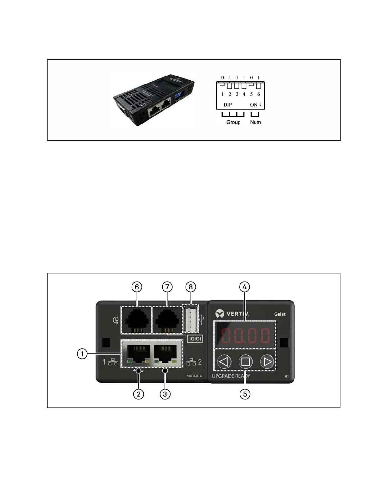
The PDUs are shipped with the IMD-03E-G module. This module provides the same features as the IMD-3E, with the addition
of a RS-232 serial port via RJ-45.
Figure 7.2 PDU Operation Display Panel
50 Proprietary and Confidential ©2024 Vertiv Group Corp. 7 Network Settings
Vertiv™ SmartRow™ 2 Infrastructure Solution User Guide