2.3 System Appearance and Components
Refer to the following figures and their accompanying tables for an overview of the SmartRow™ 2 infrastructure solution.
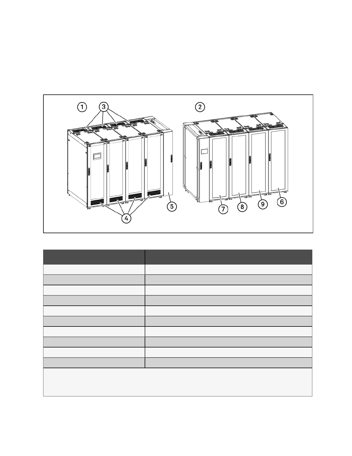
NOTE: While only three IT rack cabinets are shown in the figures, a maximum of five can be installed.
Figure 2.1 System Front and Rear View
Number Description
1 Front view
2 Rear view
3 Hot aisle emergency fan
1
4 Cold aisle emergency fan
1
5 Air conditioner - Vertiv™ Liebert® CRV CRD10 or CR019 row based cooling system
2
6 Power Management Cabinet (PMC)
7 IT rack cabinet 3
8 IT rack cabinet 2
9 IT rack cabinet 1
10 Top cable tray
NOTE:
1: Each cabinet contains one hot aisle and one cold aisle emergency fan.
2: The 10kW system uses the Vertiv™ Liebert® CRD10; the 20kW uses the Vertiv Liebert® CR019.
Table 2.1 System Front and Rear View
4 Proprietary and Confidential ©2024 Vertiv Group Corp. 2 Getting Started
Vertiv™ SmartRow™ 2 Infrastructure Solution User Guide