Note the following information when configuring the Home page:
• Use the corresponding icons for air conditioning refrigeration, air conditioning fan, and emergency fan normal
operations for animation display.
• Turn on the hot and cold channel dynamic air flow map for the air conditioner fan or emergency fan normal
operation.
• If the ITcabinet parameters, including temperature and humidity for the hot and cold aisles, exceeds the set
values, the corresponding parameters are highlighted orange on the Home page. On the contrary, the PMC
parameters fall back to the set range (and fall back the difference > the return), turning the parameters white on
the Home page.
• The front or rear cabinet doors has at least two temperature collection points. If a single point temperature
exceeds the set value, the corresponding cabinet is highlighted orange on the Home page.
• Click anywhere in the PMCbox body to enter the Power Distribution page.
• Click anywhere in the CRAC box body to enter the Thermal Management page.
• Click anywhere in the IT rack cabinet box body to enter the Environment page for that specific cabinet.
• After 10 minutes, system configurations and restart operations completed on the Home page cannot trigger
PLClogic. It cannot be linked to emergency fans, sound and light warning lights, and front door 3-color lights
triggered by the PLC of the corresponding action.
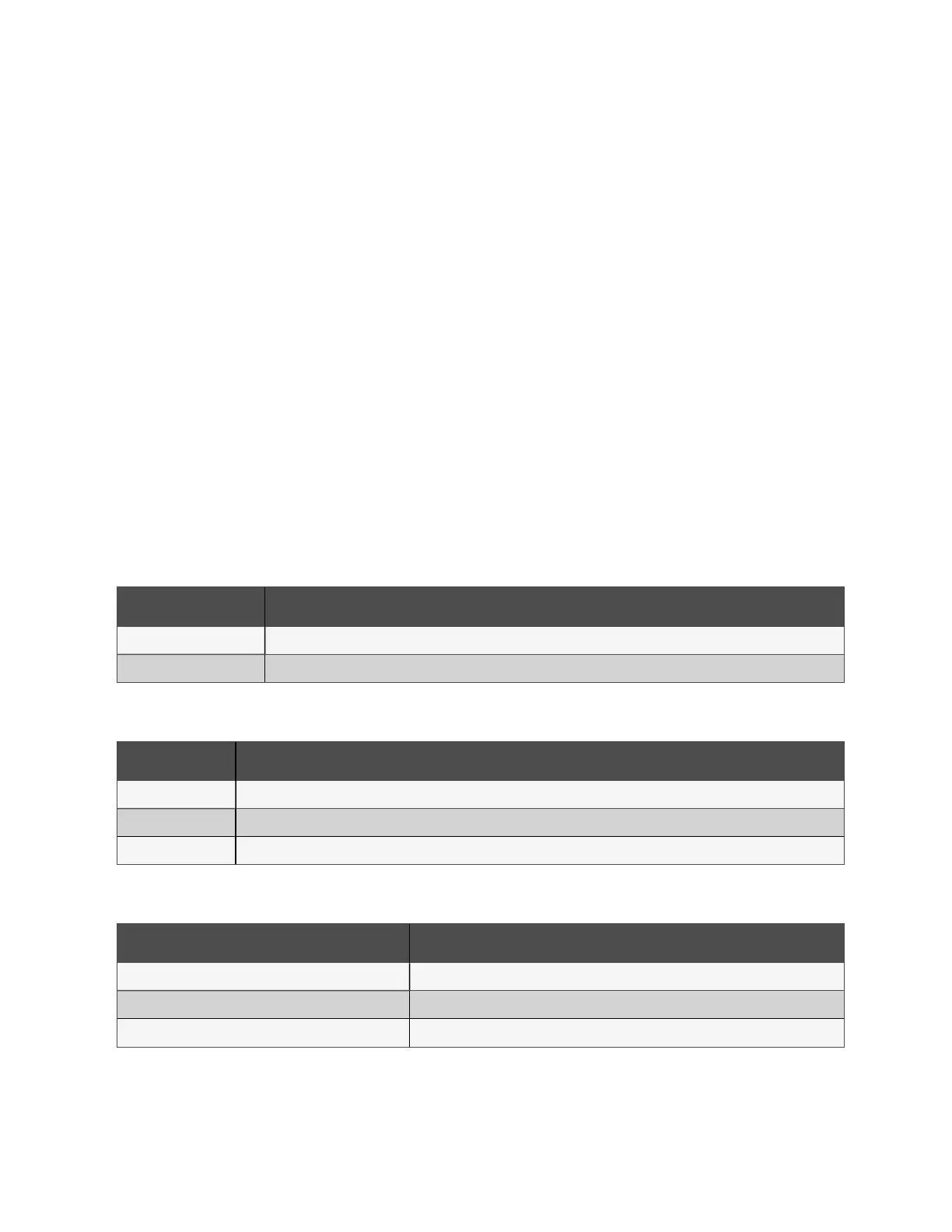
8.1.1 System function information
System function information displays on each sub-page of the LCD screen.
Function Description
Date and time Calibration can be done via the Time Calibration bar under the web page.
Service hotline For service support, use the service hotline to receive assistance via telephone.
8.1.2 System performance parameters
Parameter Description
PMC Live power is fed by the electrified input and the input phase voltage (L1/L2/L3).
IT rack cabinet Average hot channel temperature, hot channel humidity, cold channel average temperature, cold channel humidity.
Air conditioning Return air temperature, air delivery temperature.
8.1.3 Critical system parameters
Parameter Description
Emergency fan status On/Off
UPS operating status
1
Power mode / bypass mode / battery mode / standby mode
System load rate -
72 Proprietary and Confidential ©2024 Vertiv Group Corp. 8 LCDScreen Overview
Vertiv™ SmartRow™ 2 Infrastructure Solution User Guide