Edge [ii] Controller Operation Manual
SECTION 1: INTRODUCTION
OMM-139_E • 8/25/2020 Technical Support • (800) 526-0288 • Mon-Fri, 8 am - 5 pm EST Page 11 of 196
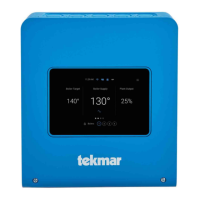
Figure 1.7: Edge Controller Front Panel Layout
All the completed settings and the Unit Event History are maintained throughout the power
cycle.
The Soft-Keys on the Controller’s front face function as follows:
Controller Front Panel Controls
Takes you to the previous screen.
Takes you to the touchscreen’s Main Menu (see Figure 1.6). If
pressed during a procedure, it aborts the procedure.
These buttons activate a selection box that can then be moved
sequentially through the editable/selectable parameters starting from
Multi-Function Bar, shows either:
• Fire Rate
• Valve Position
Parameter Indicator for both
temperature read-outs:
• LEFT: Inlet or Setpoint
temperature
• RIGHT: Outlet or System Header
temperature
Temperature scale indicator: Fahrenheit
or Celsius
Configurable temperature read-outs (2):
• LEFT: Inlet or Setpoint
temperature
• RIGHT: Outlet or System Header
temperature
Operation Mode Indicators (2):
• LEFT: Demand or Manual
• RIGHT: Manager (BST only),
COMM when communicating
Edge Controller Touchscreen: see
Section 1.8, below
onAER Indicator Light
Fault Indicator Light
Low Water Level Test buttons (2):
• TEST: Initiates Low Water test
• RESET: Resets unit after Low
Water test
![Watts AERCO Edge [ii]](https://data.easymanua.ls/products/808371/200x200/watts-aerco-edge-ii.webp)
 Loading...