6.3.5 SmartPlate Communication
The SmartPlate Communication screen provides parameters for configuring communication
between SmartPlate units and a “Manager” boiler.
NOTE:
This screen is available only after BST Cascade functionality has been enabled (see the
Unit Mode parameter in Section 6.3.1: Cascade Configuration). If the unit is configured as
a BST Manager, the parameters apply to this unit and all BST Client units.
This screen is available only after BST Cascade functionality has been enabled (see Section
6.3.1: Cascade Configuration, Unit Mode parameter). If the unit is configured as a BST
Manager, the parameters apply to this unit and all BST Client units in the cascade.
1. Go to: Main Menu → Advanced Setup → BST Cascade → SmartPlate Comm.
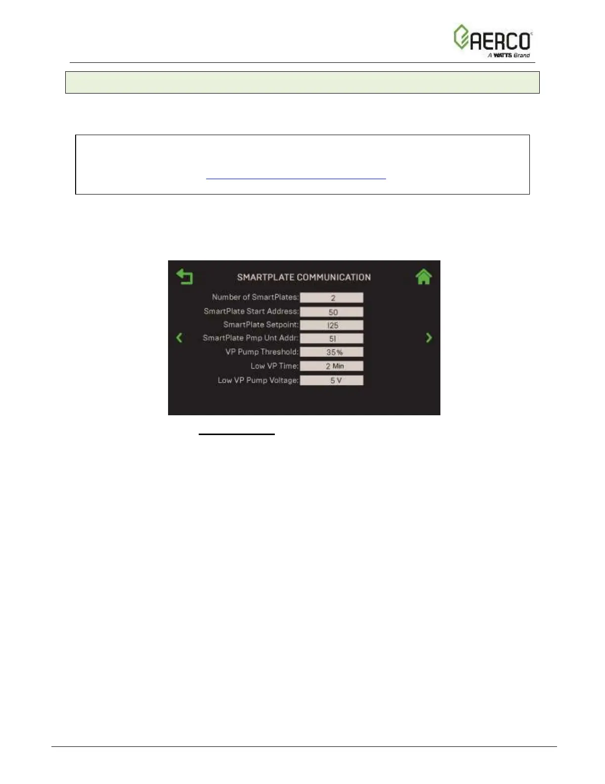
Figure 6.3.5: BST Cascade: SmartPlate Communication Screen
2. This screen contains the following parameters:
• Number of SmartPlates: Quantity of SmartPlate units in the BST Cascade.
(Range: 0 to 6)
• SmartPlate Start Address: The address of the first SmartPlate in the BST
Cascade. (Range: 50 to 54)
• SmartPlate Setpoint: The setpoint of the SmartPlate units. (Range: 0 to 140°F)
• SmartPlate Pmp Unit Addr: Address of the SmartPlate whose feedback will be
used to control the variable speed DHW pump. (Range: 0 to 255)
• VP Pump Threshold: SmartPlate Valve Position threshold, which lowers pump
speed from 10V. (Range: 20% to 70%)
• Low VP Time: Amount of time SmartPlate is in VP (Valve Position) Pump Threshold
before reducing DHW pump speed. (Range: 1 to 15 min.)
• Low VP Pump Voltage: The voltage to which the pump is reduced to after
SmartPlate units meets VP Pump Threshold and Low VP Time has expired.
(Range: 2 to 8 V)
![Watts AERCO Edge [ii]](https://data.easymanua.ls/products/808371/200x200/watts-aerco-edge-ii.webp)
 Loading...