Figure 6.3.4.5: Operating Controls: Reserve Unit Control Screen
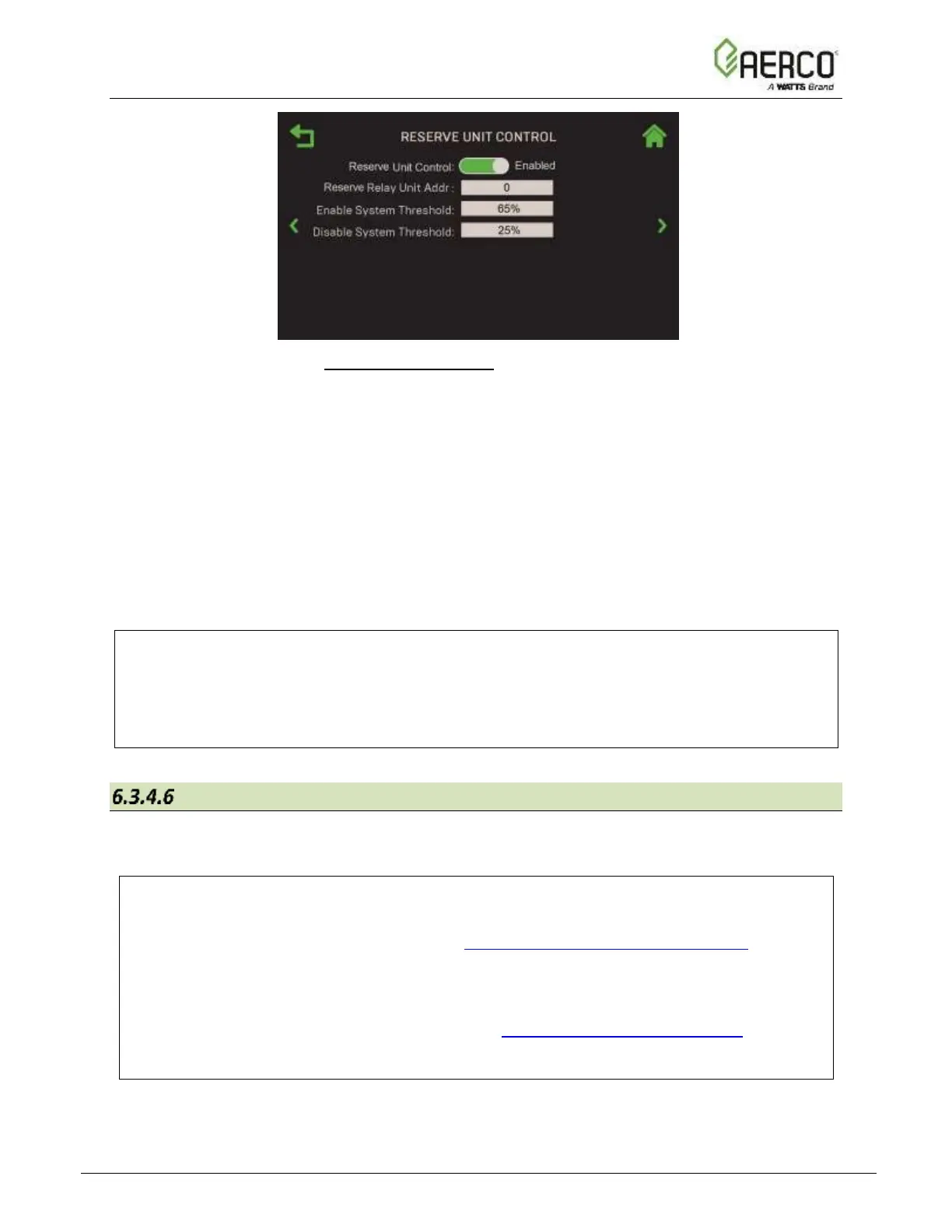
2. To enable a Reserve Unit, set Reserve Unit Control to Enabled.
3. If Reserve Unit Control = Enabled, the following additional parameters are available:
• Reserve Relay Unit Addr: The address of the Edge unit that the reserve boiler is
connected to via its reserve unit relay. (Range: 0 to 16 or max address in the plant)
• Enable System Threshold: The plant fire rate that activates (closes) the Reserve
Unit to fire. (Range: 20% to 100%)
• Disable System Threshold: The plant fire rate that deactivates (opens) Reserve
Unit; should be at least 20% below Enable System Threshold.
(Range: 20% to 90%)
NOTE:
In the event of a power outage, the BST Manager will not be able to tell the Reserve Unit to
turn on. In the case where the Reserve Unit is also acting as a backup unit, a separate,
normally open relay should be installed so that when a generator is operating the Reserve Unit
will be active as well.
Setpoint Range
The Setpoint Range screen includes all Setpoint Limiting and Setpoint Setback parameters for
all units in the cascade.
NOTES:
• This screen is available only after BST Cascade functionality has been enabled (Unit
Mode = BST Client or BST Manager in Section 6.3.1: Cascade Configuration). If the
unit is configured as a BST Manager, the parameters apply to this unit and all BST
Client units. If the unit is configured as a BST Client, the parameters configured on the
BST Manager will take precedence.
• Some of the parameters below also appear in Section 6.6.2.3: Setpoint Range, which is
available only to standalone units. This section is available when that section is
unavailable (see previous bullet).
![Watts AERCO Edge [ii]](https://data.easymanua.ls/products/808371/200x200/watts-aerco-edge-ii.webp)
 Loading...