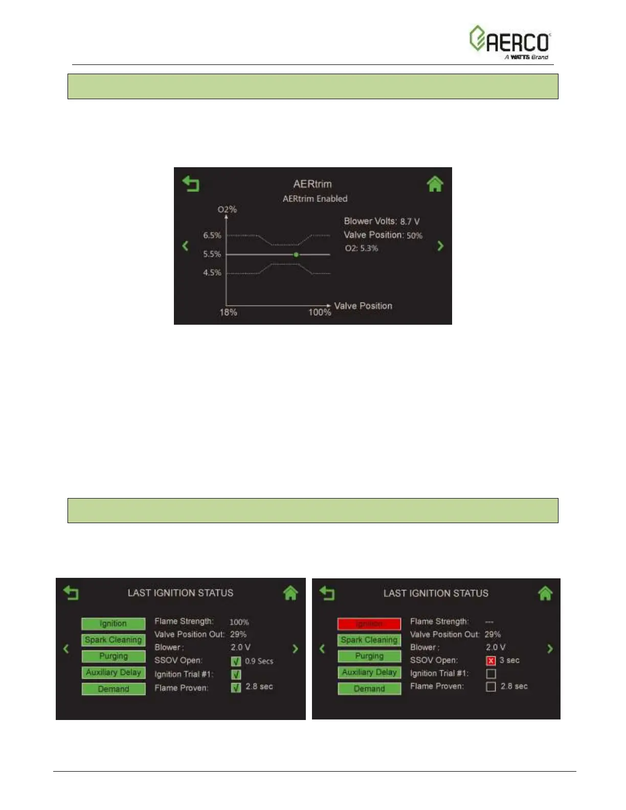
7.10 AERtrim
The AERtrim screen displays the AERtrim state and a graph showing the current valve position,
O
2
level and blower voltage. It can be displayed on any unit on which AERtrim is both activated
and enabled (see Section 6.6.1). The AERtrim status (under the screen title) will be Disabled if
the function is disabled after being successfully activated.
Figure 7.10: AERtrim Status
This screen displays the following:
• The O
2
reading, current valve position and blower voltage in numerical form.
• A graph showing the O
2
level associated with current valve position; the green dot on the
graph represents the current O
2
level of the unit.
o If the unit is not firing (or AERtrim is disabled), the green dot will not appear.
o The solid line represents the O
2
target for a given valve position. Note that this
is model and/or site specific.
o The two dotted lines represents the O
2
target band for a given valve position.
7.11 Ignition Sequence (summary)
The Last Ignition Status screen displays a summary of the last ignition sequence, whether it is
a successful or not. If unsuccessful, it shows the step that failed in red, and one or more check
boxes and the status box has red X.
IGNITION SUCCESSFUL IGNITION FAILED
Figure 7.11: Ignition Screen
![Watts AERCO Edge [ii]](https://data.easymanua.ls/products/808371/200x200/watts-aerco-edge-ii.webp)
 Loading...