7.1.1 Demand
1. Upon a demand for heat, the Demand rectangle turns green, and, if the sequence has a
delay timer, those timers display appropriate values.
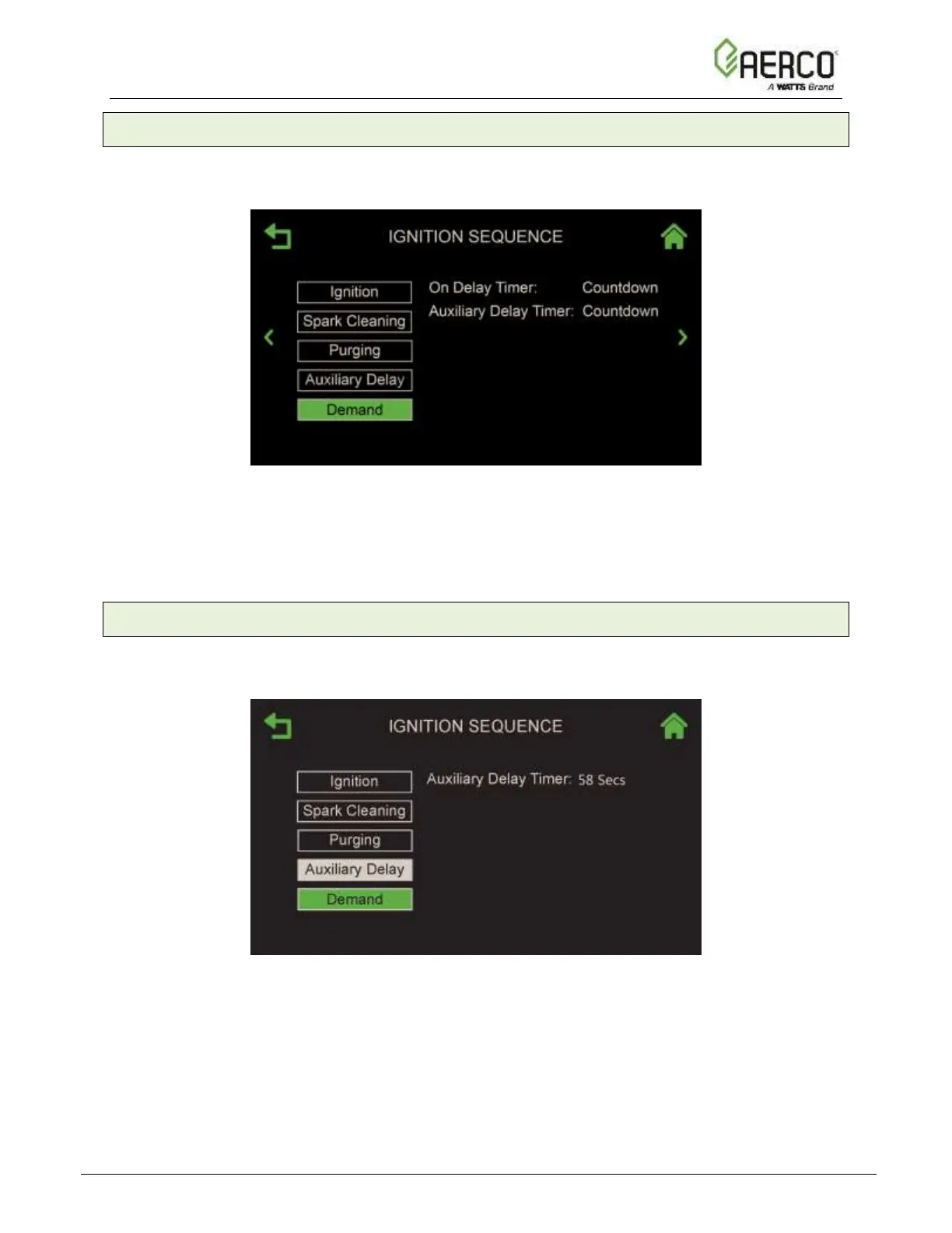
Figure 7.1.1: Ignition Sequence Step 1 – Demand
2. Upon expiration of the internal 4 second IGST Demand delay and the unit progresses to the
Auxiliary Delay sequence.
7.1.2 Auxiliary Delay Timers
1. Upon expiration of the internal 4 second IGST Demand delay, On Delay Timer starts,
followed by Auxiliary Delay Timer (if any). In both cases, the displays the count down.
Figure 7.1.2: Ignition Sequence Step 2 – Auxiliary Delay
2. When the On Delay Timer and all the interlock switches are closed, the Auxiliary Delay
rectangle turns green and the unit progresses to the Purging sequence.
• If the interlock switches are closed and On Delay time has expired, the Auxiliary
Delay rectangle immediately changes to green, allowing for the purge cycle to begin.
• If the any of the interlock switches are not closed when the auxiliary timer expires, the
Auxiliary Delay rectangle turns red and the correspond interlock fault is displayed.
![Watts AERCO Edge [ii]](https://data.easymanua.ls/products/808371/200x200/watts-aerco-edge-ii.webp)
 Loading...