3. Depending on your choice, the following parameters appear (# = 1, 2 or 3, depending on the
value of Select Output):
• Aout # Name:
o Aout 1 and Aout 3: Can be set to Fire Rate or Other.
o Aout 2: Can be set to Valve, Fire Rate or Other.
• Aout # Signal: Displays the signal for this output: Aout 1 = 1-10v, Aout 2 and
Aout 3: Appears only if Select Output = Spare Analog Out 3: A read-only
display of the signal associated with Spare Analog Out 3.
• Aout # Min Fire Rate and Aout # Max Fire Rate: Enter the minimum and
maximum fire rates. The analog voltage signal is linearly mapped to the firing rate
values. (Min Fire Rate Range: 0% to 50%, Max Fire Rate Range: 51% and 100%).
• Rem Spr Aout # Add: (Remote Spare Analog Output # Address, where # is the
output chosen in Step 2, 1, 2 or 3): Specify the address of the unit to which the
analog output signal is sent. (Range: 0 to 16)
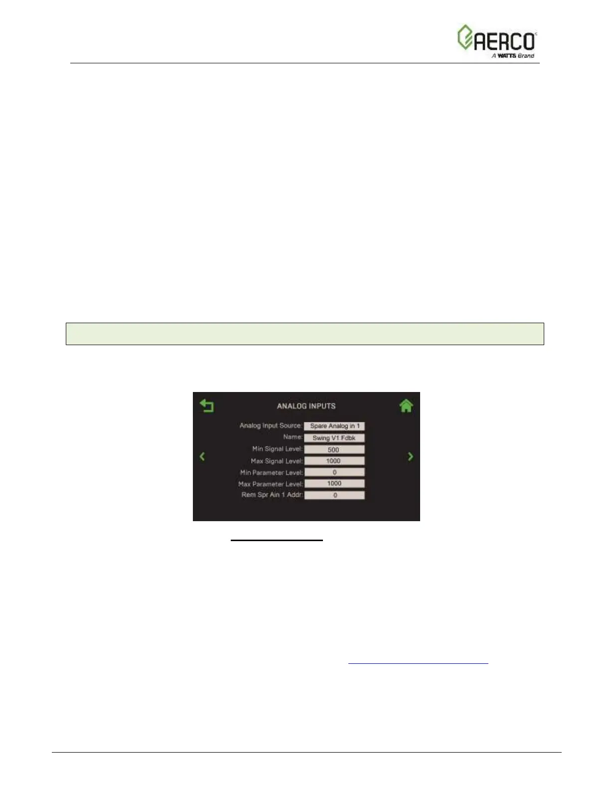
6.5.4 Analog Inputs
Analog Input menu allows you to configure all available programmable analog inputs.
1. Go to: Main Menu → Advanced Setup → Ancillary Device → Analog Inputs.
Figure 6.5.4: Ancillary Device: Analog Inputs Screen
2. Choose the analog input you want to configure. These inputs attach to the unit’s I/O box
strip J5, on the pins shown below.
• Spare Analog In 1 – pin 3 Spare Analog In 1+ pin 4 Spare Analog In 1-
• Spare Analog In 2 – pin 5 Spare Analog In 2+ pin 6 Spare Analog In 2-
• Spare Analog In 3 – pin 1 Spare Analog In 3+ pin 2 Spare Analog In 3-
3. Select the name for the input chosen in Step 2 in the Name field. (Note, the combination
chosen in Steps 2 and 3 determines what appears in Section 3.3.3: Analog Inputs.)
![Watts AERCO Edge [ii]](https://data.easymanua.ls/products/808371/200x200/watts-aerco-edge-ii.webp)
 Loading...