www.wegener.com 800009-01 Rev. J 13
iPump 6400 User’s Manual
2.3 iPump 6400 Connections
Before applying power, make the following connections to your iPump 6400. Refer to
Table 2.1 on page 14 for connector details and to Figure 2.2: iPump 6400 rear-panel
connector locations
for placement.
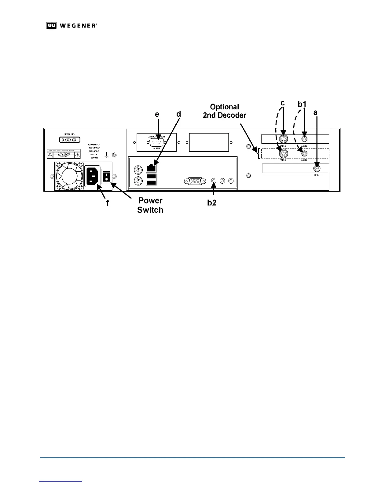
Figure 2.2: iPump 6400 rear-panel connector locations
1. Connect the L-band output from your antenna's LNB or from your multiswitch to the
extender cable on your
iPump 6400
's input RF port [
a
]. (A BNC connector is used here for
iPump 6400
s with the ASI input option.)
2. Connect a suitable audio monitor or monitors to the
iPump 6400
's audio port(s) [
b1
] (on
both decoders if your
iPump 6400
includes a second decoder). Also connect audio
monitoring to the auxiliary audio port [
b2
] if your
iPump 6400
includes that option. See
Table 2.1
.
Note: See Figure 2.3: Digital output decoder connector layout on page 15 for an
illustration and audio/video connector details if your
iPump 6400 is equipped with an
optional decoder with digital outputs.
3. Connect a suitable video monitor or monitors to the
iPump 6400
's video port [
c
] (on both
decoders if your
iPump 6400
includes a second decoder). (See
Table 1.1: iPump 6400
options key
on page 4.)
4. Connect your LAN line to the
iPump 6400
's Ethernet port [
d
]. (Refer to
Table 2.3: iPump
6400 LAN connector pin functions
on page 15.)
5. If desired, connect the Alarm port [
e
] to your equipment to provide contact closures and
openings during alarms or on command from
Compel
. (Refer to
Table 2.2: iPump 6400
Alarm connector pin functions
on page 15.)
6. Finally, connect the supplied ac power cord to the
iPump 6400
's IEC receptacle [
f
] and to a
100-to-120 Vac or 200-to-240 Vac source.
Note: Do not connect devices to the mouse, keyboard, and other connectors not
described here. They are for factory use only.