Installation
16 800009-01 Rev. J www.wegener.com
Table 2.4: Digital output decoder connectors
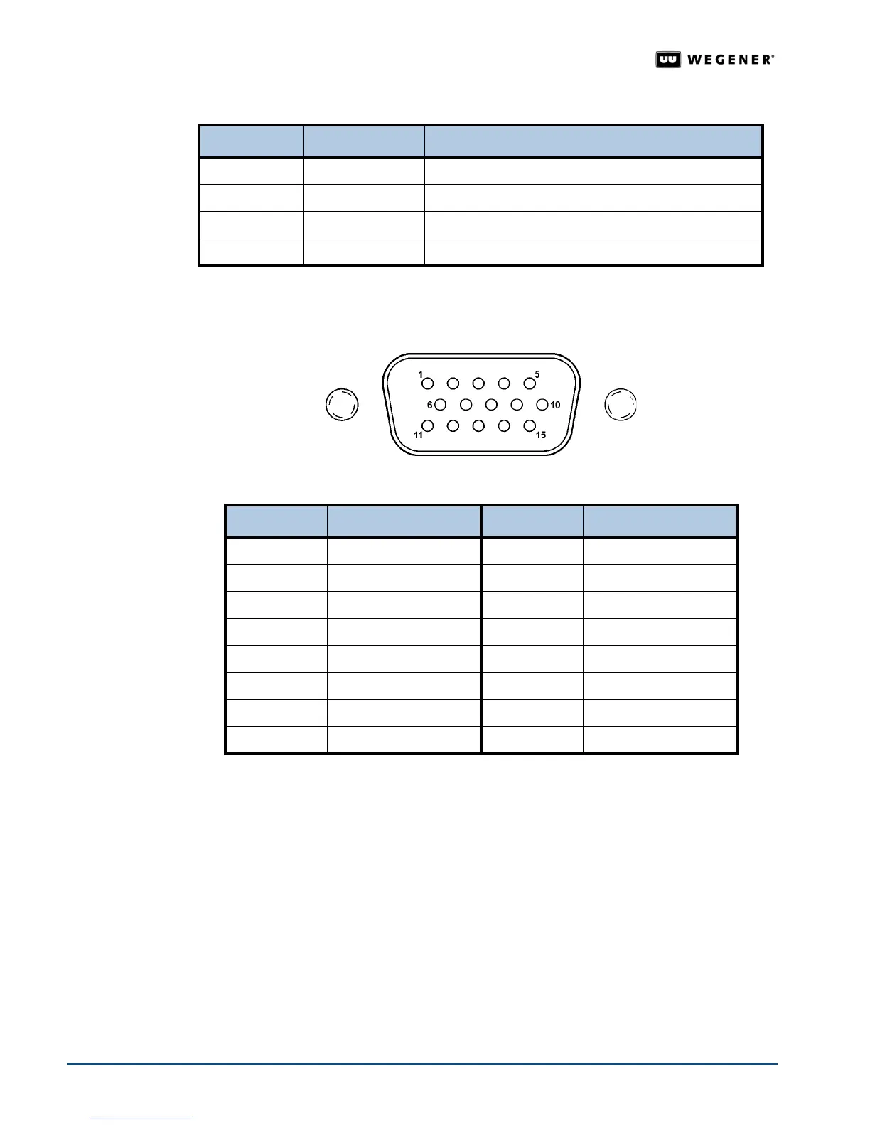
Pinout details for the balanced analog and AES/EBU digital audio connector are shown in
Figure 2.4 and Table 2.5 below.
Figure 2.4: Balanced analog and AES/EBU digital audio connector
Table 2.5: Balanced analog and AES/EBU digital audio connector pin functions
Pro Audio
Decoder
The output connectors for the professional audio model of the iPump 6400 look somewhat
different than the standard video decoder connectors. The
iPump 6400 Pro Audio Decoder
allows streams of different sample-rates and formats to be mixed together and sent to both
analog and digital AES/EBU outputs. Synchronization capabilities include an AES/EBU
sync input and Word clock input and output. Special cables are required for connection to
both the analog and digital outputs. Pinout details for the Pro Audio Decoder connectors are
shown in
Figure 2.5 below.
Ref Number Connector Type Signal Description
1 BNC Serial Digital Video Out
2 BNC Composite Video Out
3 BNC Genlock Reference In (Not currently supported)
4 DB-15 HD Balanced Analog Audio and AES/EBU Digital Audio Out
Pin Number Function Pin Number Function
1 Analog Ch B (Left +) 9 Analog Ch B (Right -)
2 Analog Ch A (Left -) 10 Analog Ch A (Right -)
3 Ground 11 Ground
4 Analog Ch B (Right +) 12 AES Ch B +
5 Analog Ch A (Right +) 13 AES Ch B -
6 Analog Ch B (Left -) 14 AES Ch A -
7 Analog Ch A (Left +) 15 AES Ch A +
8 Ground