www.wegener.com 800009-01 Rev. J 15
iPump 6400 User’s Manual
Table 2.2: iPump 6400 Alarm connector pin functions
Ethernet/LAN
Port Details
The iPump 6400's 10/100baseT (autosensing) Ethernet port has the following pin functions.
Table 2.3: iPump 6400 LAN connector pin functions
Optional
Decoder with
Digital Output
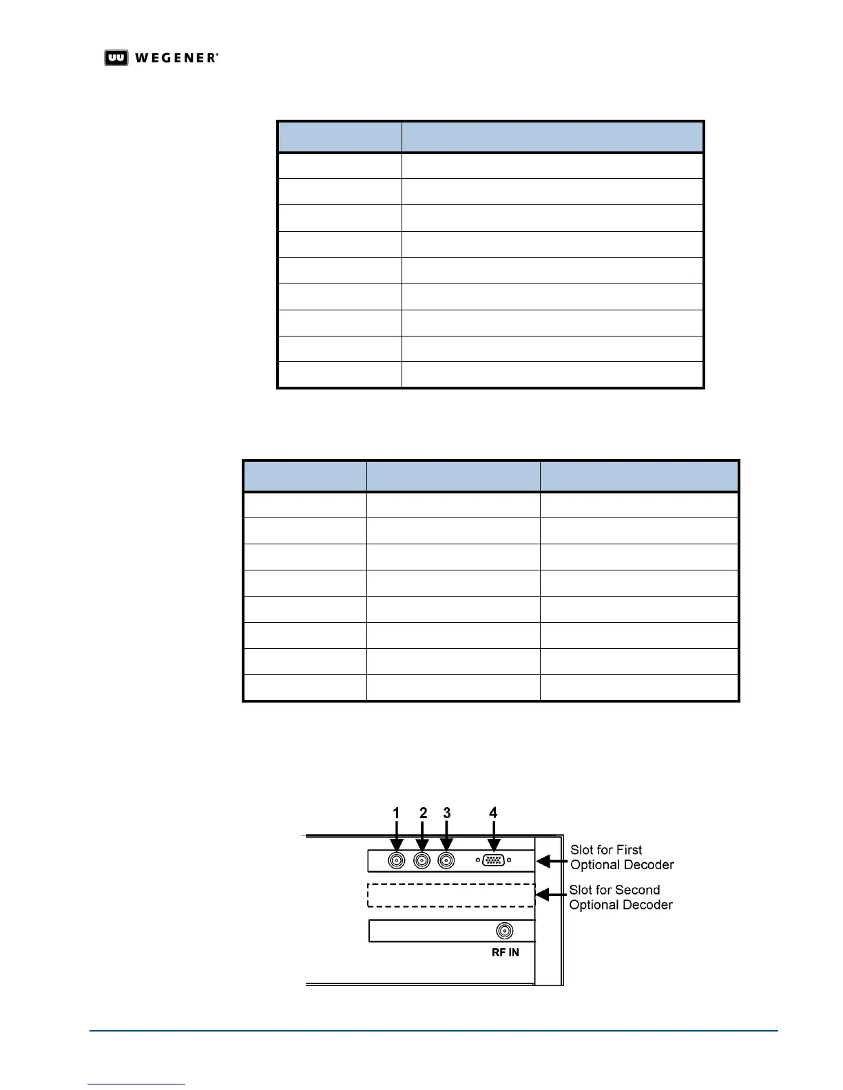
Connector details are somewhat different for iPump 6400s having the optional decoder with
digital audio and video output.
Figure 2.3 below illustrates the
rear-panel layout of this
optional decoder. Connector details are listed in
Table 2.4
.
Figure 2.3: Digital output decoder connector layout
Pin Number Function
1 Alarm common
2 Alarm Normally Open
3 Contact Closure Out Common
4 No Connection
5 Contact Closure Input
6 Alarm Normally Closed
7 No Connection
8 Contact Closure Out Normally Open
9 Ground
Pin Number Name Description
1 TX_D1+ Transmit Data+
2 TX_D1- Transmit Data-
3 RX_D2+ Receive Data+
4 Unused
5 Unused
6 RX_D2- Receive Data-
7 Unused
8 Unused