www.wegener.com 800009-01 Rev. J 17
iPump 6400 User’s Manual
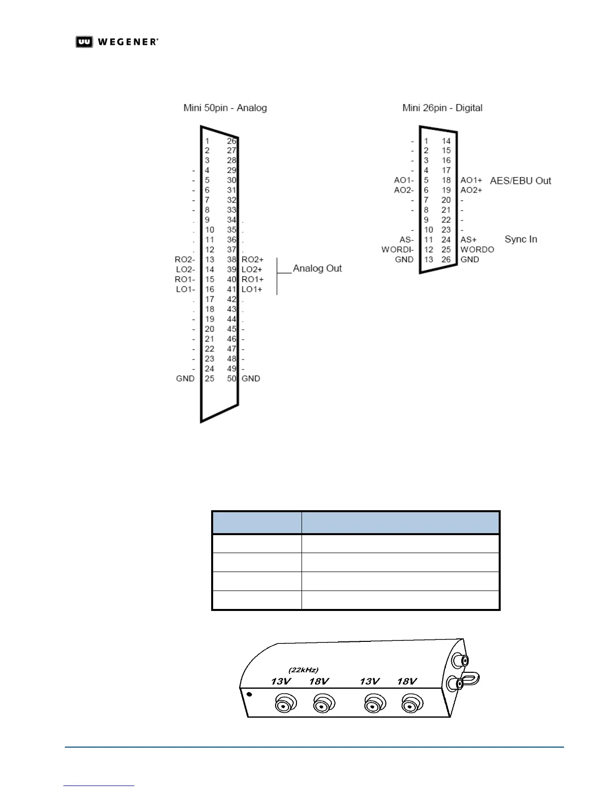
Figure 2.5: Connectors for the Pro Audio Decoder
Multiswitch
Connection
Details
When operating a multiswitch, use Table 2.6 to identify the line signals corresponding to
each
iPump 6400 RF port selection. On a typical multiswitch (as in Figure 2.6 below), these
ports will be in order from left to right as viewed from the side holding the input connectors.
Table 2.6: RF port selection signals
Figure 2.6: Typical RF multiswitch
Port Number Signal
1 13V with 22 kHz tone
2 18V with 22 kHz tone
3 13V without tone
4 18V without tone