Maintenance
1903−1/A1
Winterthur Gas & Diesel Ltd.
1/ 3
Tension Checks and Replacement Procedure
Tools:
1 Rod 94005 2 Coupling elements 94934G
2 Pre-tensioner 94180 3 HP hoses 94935
1 Connection block 94934 1 Hydraulic unit 94942
1 Hydraulic distributor 94934A
1. General 1..........................................................
2. Tension Check 1....................................................
3. Tie Rods − Replace 2...............................................
3.1 Preparation 2.................................................
3.2 Removal 2....................................................
3.3 Installation 2.................................................
3.4 Apply Tension 3..............................................
1. General
We recommend that you do a check of the tension of all tie rods one year after
commissioning, refer to 0380−1 Maintenance Schedule, Tie rod. If necessary, apply
tension to the specified value. Random checks can be done during overhauls.
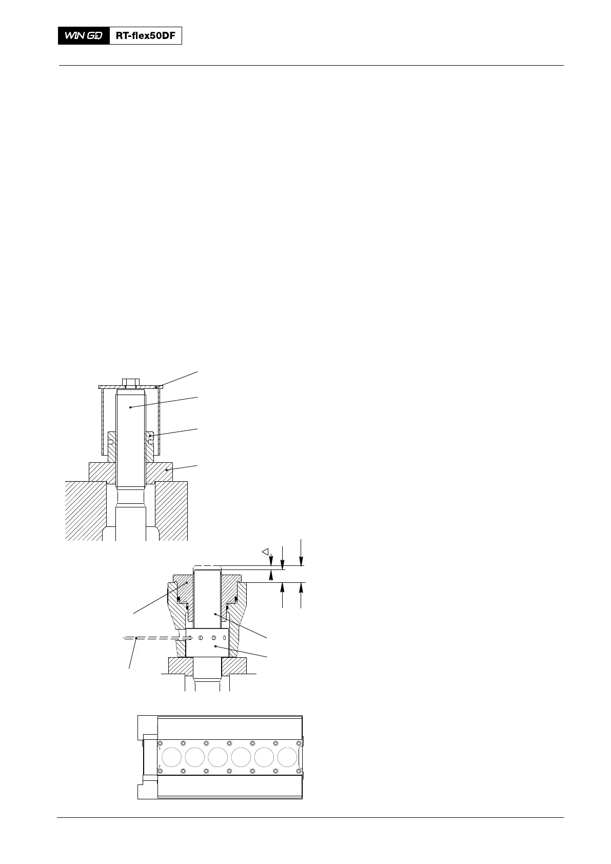
2. Tension Check
1) Remove the protection cover (1, Fig. 1)
from all tie rods (2).
2) Clean the surfaces of the intermediate
ring (4).
Note: Start with the tie rods (a−a) in the
middle of the engine, then b−b,
etc).
3) Attach the two pre-tensioners (94180)
to two tie rods (2, a−a Fig. 1).
4) Apply a tension of 1500 bar to the tie
rods (2), refer to 9403−4.
5) If possible, tighten the round nuts (3).
6) If the round nut (3) cannot move, do
step a) to step b):
a) Put a round bar (94005) through
the opening of the jack and into a
hole in the round nut .
b) Use a hammer to loosen, then
tighten the nut. Make sure that the
edge of the hole has no
deformation.
7) Remove the pre-tensioners (94180),
refer to 9304−1.
8) Apply a layer of Molykote paste G to
the threads of the tie rod (2) to prevent
corrosion.
9) Install the protection cover (1).
10) Do step 3) to step 9) for the remaining
tie rods.
Tie Rod
2016
2
3
4
1
WCH00667
ecab dfg
ecab dfg
L
L
1
L
94005
94180
2
3
Fig. 1