Maintenance
1132−2/A1
Winterthur Gas & Diesel Ltd.
3/ 14
WARNING
Injury Hazard: Do not use
the thrust device 94110 as
a lifting device. Injury to
personnel can occur.
CAUTION
Damage Hazard: Use the
thrust device (94110) only
for the removal of the main
bearing covers. Damage to
equipment can occur if you
use incorrect equipment
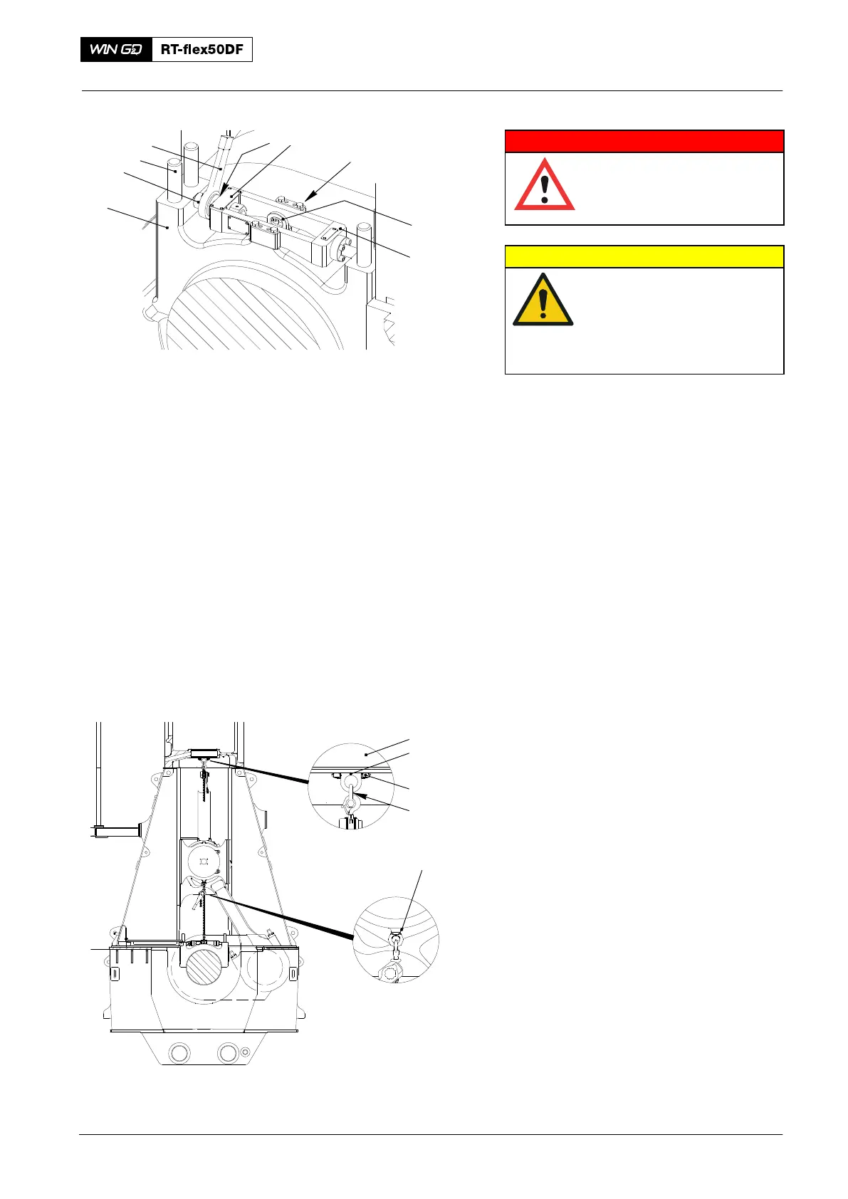
5) Apply tension to the four elastic studs
(6, Fig. 3). and remove their nuts, refer
to 1132−1.
6) Attach the lug (94116B) to the main
bearing cover (4).
7) Make sure that the thrust device
(94110) is clean.
8) Apply Molykote G-Rapid Plus to the
spindle of the special screw (1) and the
thrust piece (5).
9) Attach the thrust device (94110) as
given in the instructions on the name
plate (2).
10) Turn back fully the spindle.
11) Attach the slugging wrench AF60.
12) Attach the thrust device (94110) to the
main bearing cover (4).
13) Put the four screws (3) in the positions
shown.
14) Torque the four screws (3) to 24 Nm.
15) Use the slugging wrench to turn the
special screw (1) and expand the main
bearing cover (4).
2.2 Main Bearing Cover −
Removal
1) Attach the eye bolt (94040−M20, Fig. 4)
to the guide shoe.
2) Torque the eye bolt (94040−M20) to
115 Nm.
3) Attach the rings (94332) and shackle
(94018B) to the cylinder block (1).
4) Torque the screws (2) to 200 Nm.
2016
Main Bearing − Removal and Installation
Fig. 3
018.595/09
94116
94110
3
2
1
4
5
7
6
018.597/09
1
94332
2
94018
94040−M20
Fig. 4