Maintenance
5556−1/A1
Winterthur Gas & Diesel Ltd.
7/ 13
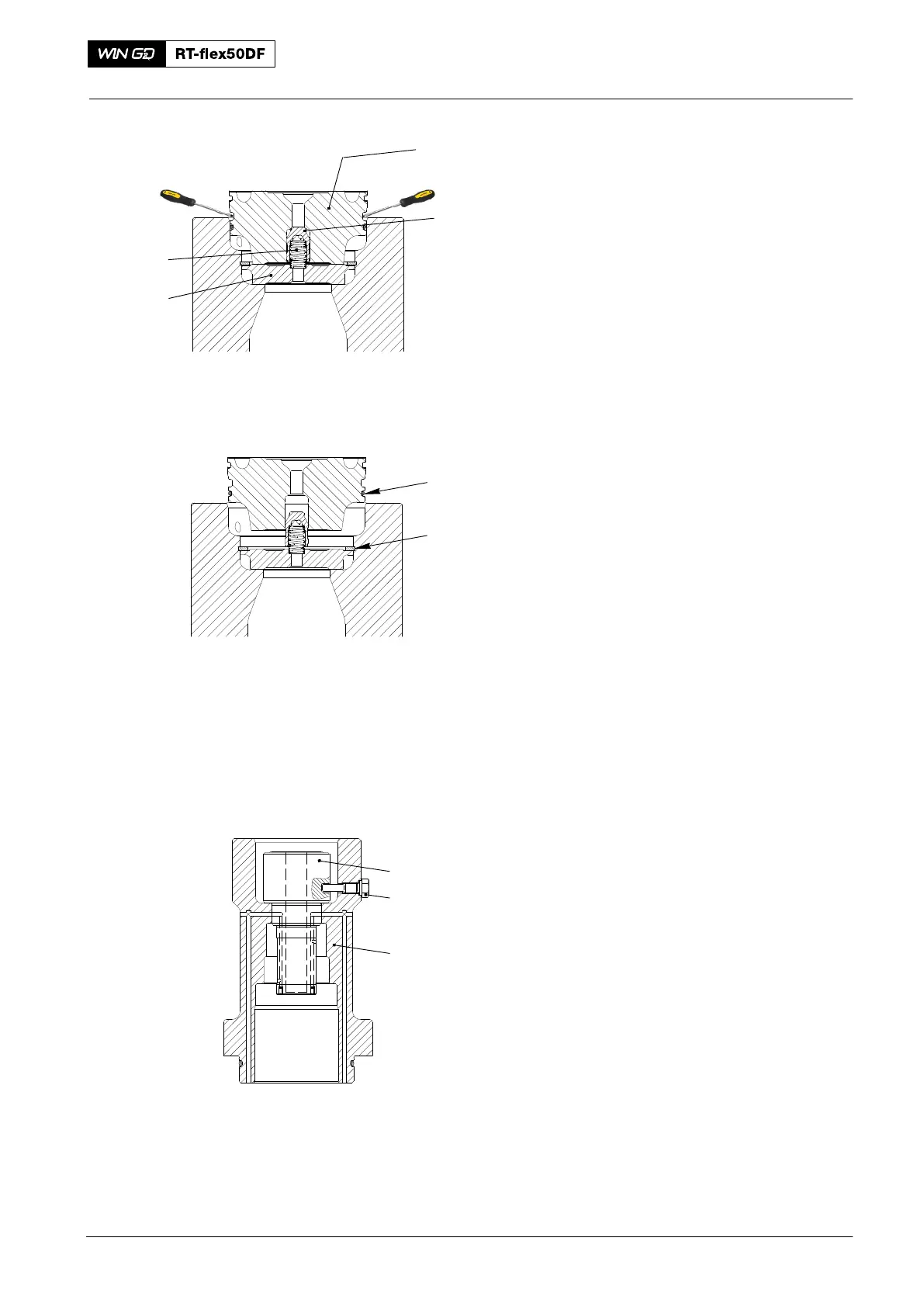
3.5 Non-return Valve − Removal
1) Put the two applicable screwdrivers in
the nut of the valve block (1, Fig. 9).
2) Use the two screwdrivers as levers to
push out the valve block (1). Make sure
that you do not cause damage to the
nut of the valve block.
Note: The non-return valve must be
replaced as a unit only, i.e. valve
block (1), valve body (2),
compression spring (4) and
intermediate disc (3).
3) Remove the circlip (6, Fig. 10).
4) Remove and discard the O-ring (5).
4. Fuel Pump − Assemble
4.1 Preparation
1) Clean all parts.
2) Do a check the condition of all parts. If
necessary, replace damaged parts.
3) Use a low-pressure air supply to make
sure that all bores in the housings and
pump cylinder (1, Fig. 11) are clear.
4) Replace all O-rings and rod seal rings.
4.2 Pump Cylinder −
Installation
1) Attach the top housing (3) vertically to
the work bench.
2) Align the groove in the pump cylinder
with the bore for the screw (2) in the
top housing (3).
3) Carefully put the pump cylinder (1) into
the top housing (3).
4) Attach the pump cylinder (1) to the top
housing (3) with the screw (2).
Note: Make sure that there is a clearance
between the screw (2) and the
base of the groove.
Fuel Pump: Removal, Disassemble, Assemble, Installation
2016
019.235/10
Fig. 9
3
4
6
5
1
2
Fig. 10
33
32
5
008.654/00
Fig. 11
1
2
3