Maintenance
3303−5/A2
Winterthur Gas & Diesel Ltd.
1/ 5
Top End Bearing − Bearing Cover Removal and
Installation
Tools:
2 Lifting rings 94332 2 Manual ratchets H1, H2, 94016−007
1 Lifting tool 94335 2 Manual ratchets H3, H4 94016−001
1 Spur-geared chain block H4 94017−021 4 RUD-eye bolt EB1, EB2 94040−M8
1 Work platform 94142 1 Double sling chain 94666I
2 Lifting boss 94333A 2 Suspension chains 94333B
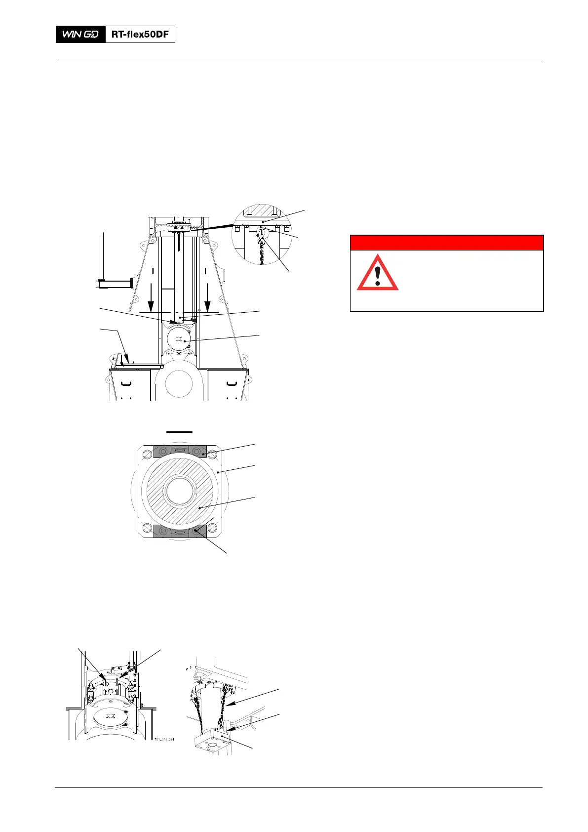
1. Piston − Lift and Hold
WARNING
Injury Hazard: Before you
operate the turning gear,
make sure that no
personnel are near the
flywheel, or in the engine.
1) Read and obey the data in 0012−1
General Guidelines for Lifting Tools.
2) Operate the turning gear to move the
the crank of the applicable cylinder to
BDC.
3) Attach the work platform (94142,
Fig. 1), refer to 3301−1.
4) Remove the nuts of the elastic studs on
the piston rod foot, refer to 9403−4.
5) Attach the bosses (94333A) to the
piston rod foot (3) with the Allen four
screws (5).
6) Attach two eye bolts (EB) to the piston
rod gland support (1).
7) Attach the chains (94333B) to the eye
bolts (EB).
8) Remove the work platform (94142).
9) Operate the turning gear to move the
crank to the exhaust side sufficiently to
attach the chains (94333B, Fig. 2) to
the bosses (94333A).
Note: During step 10), make sure that the
dowel pins (7) do not stay in the
piston rod foot (5).
10) Operate the turning gear to lower the
piston until the elastic studs (6) come
out of the piston rod foot (5).
Connecting Rod
2016
I
I
1
94333B
Fig. 1
EB
94333A
94142
3
2
Fig. 2
94333B
94333A
6
7
013.552/05
94333A
3
2
4
013.553/05
I - I
5