Maintenance3303−4/A2
Winterthur Gas & Diesel Ltd.
6/ 6
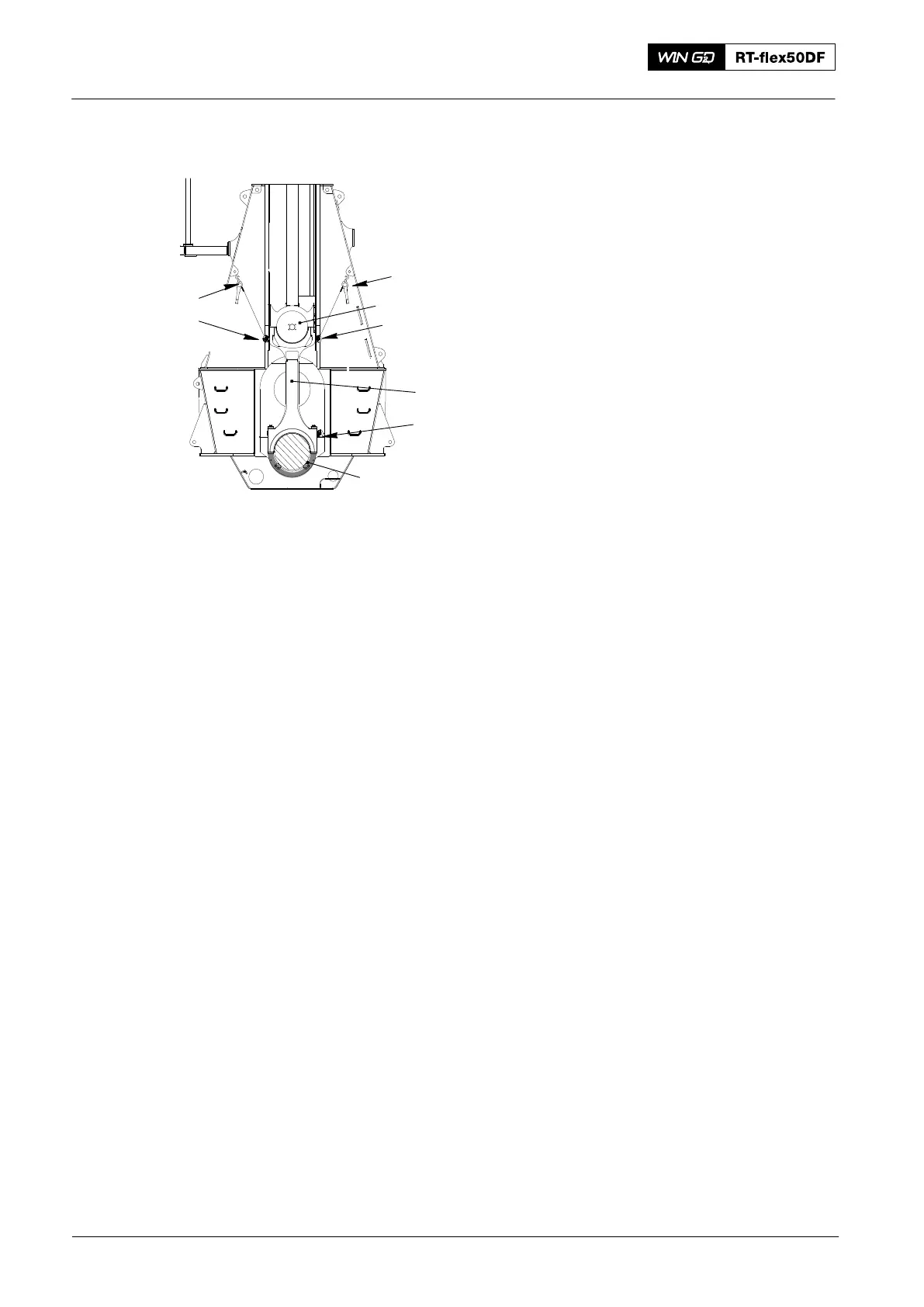
16) Operate the turning gear to move the
crank clockwise to BDC. Make sure
that the connecting rod stays in the
vertical position (see Fig. 10).
17) Attach the manual ratchet (H1) to the
eye bolt (EB1).
18) Remove the eye bolt (EB3).
19) Remove the holder (94331).
5. Completion
Note: If the piston is installed, refer to
3303−2, paragraph 5.1 step 18) to
step 26) to lower the
crosshead (1).
Note: If the piston is removed, refer to
3303−3, paragraph 5.2 step 18) to
step 26) to lower the
crosshead (1).
1) Install the bottom end bearing cover,
refer to 3303−2.
2) Measure the clearances, refer to
0330−1.
3) Remove all tools and equipment from
the work area.
2016
Connecting Rod: Removal and Installation
94331
2
H2
H1
EB1
1
EB2
EB3
Fig. 10