Maintenance
2708−4/A1
Winterthur Gas & Diesel Ltd.
1/ 1
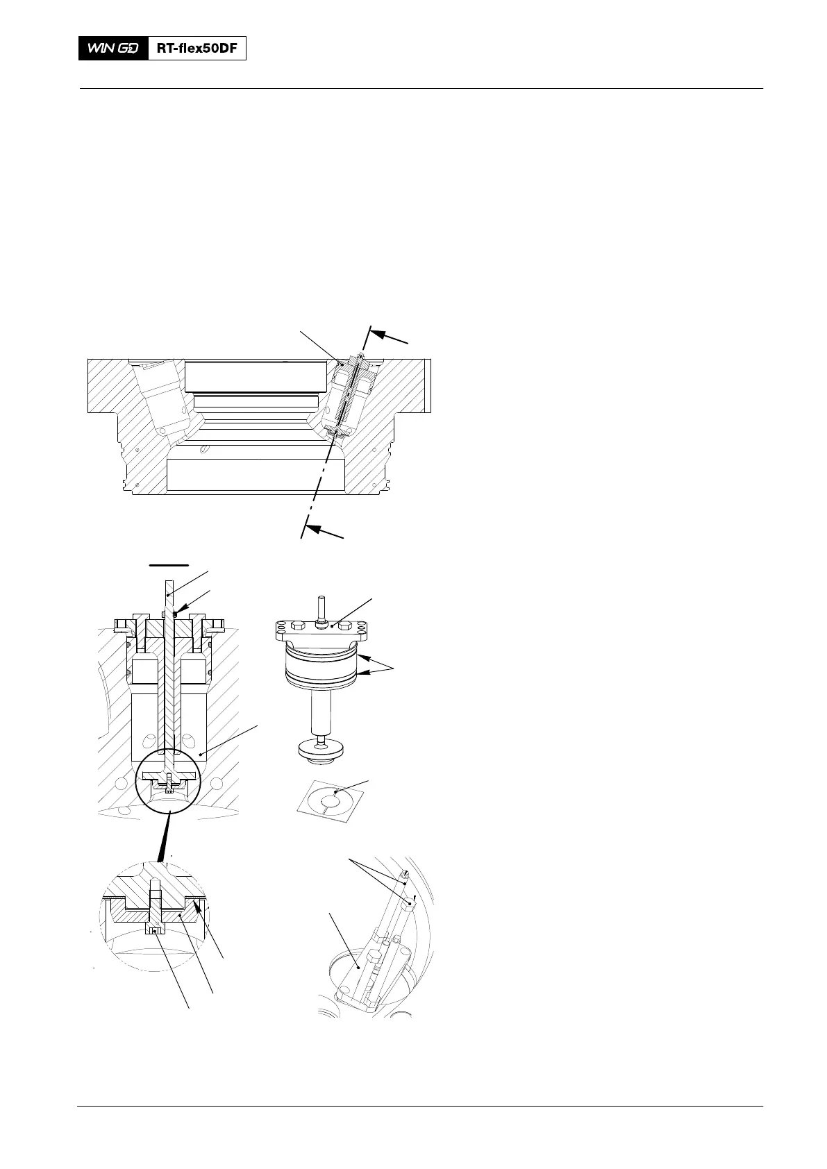
Sealing Face for Pilot Injection Valve Position − Grind
Tools:
1 Grinding device 94270−02 2 Stud bolts 94270F
1 Stencil 94270−2D
1. Procedure
1) Make sure that the stop sleeve (4) is
attached to the spindle (1) of the device
(94270−02).
2) Make sure that the O−rings (2) are
serviceable.
3) Use the applicable grade of emery
cloth related to the quantity of metal
you want to remove.
4) Put the stencil (94270−2D) on the
emery cloth.
5) Use a pencil or a ball pen to make the
inner shape (5).
6) Cut out accurately the shape.
7) Attach the shape (5) to the device
(94270−02) with the clamp (6) and the
the Allen screw (7).
8) Torque the Allen screw (7) to 8.0 Nm.
9) Apply a thin layer of oil to the
O−rings (2).
10) Attach the device (94270−02) to the
cylinder cover with the stud bolts
(94270F) as shown.
11) Attach an electric drill to the spindle (1).
12) Operate the electric drill at a maximum
of 500 rpm.
Note: During step 12, do not grind more
than 1.0 mm from the bottom of
the bore (3).
13) Apply a light pressure and start
grinding.
14) Regularly remove the unwanted
material from the device (94270−02)
and the bore (3).
15) Make sure that the circular marks
around the sealing face of the bore (3)
are concentric.
16) Change the emery cloth for a smoother
grade, then do step 3) to step 15) again
until you get a smooth finish.
17) Clean the bore (3).
Pilot Injection Valve
2018
Fig. 1
I
I
94270−02
I - I
1
94270−02
94270−2D
2
5
6
7
4
3
94270F
94270−02
WCH00864