Maintenance
8733−1/A1
Winterthur Gas & Diesel Ltd.
3/ 3
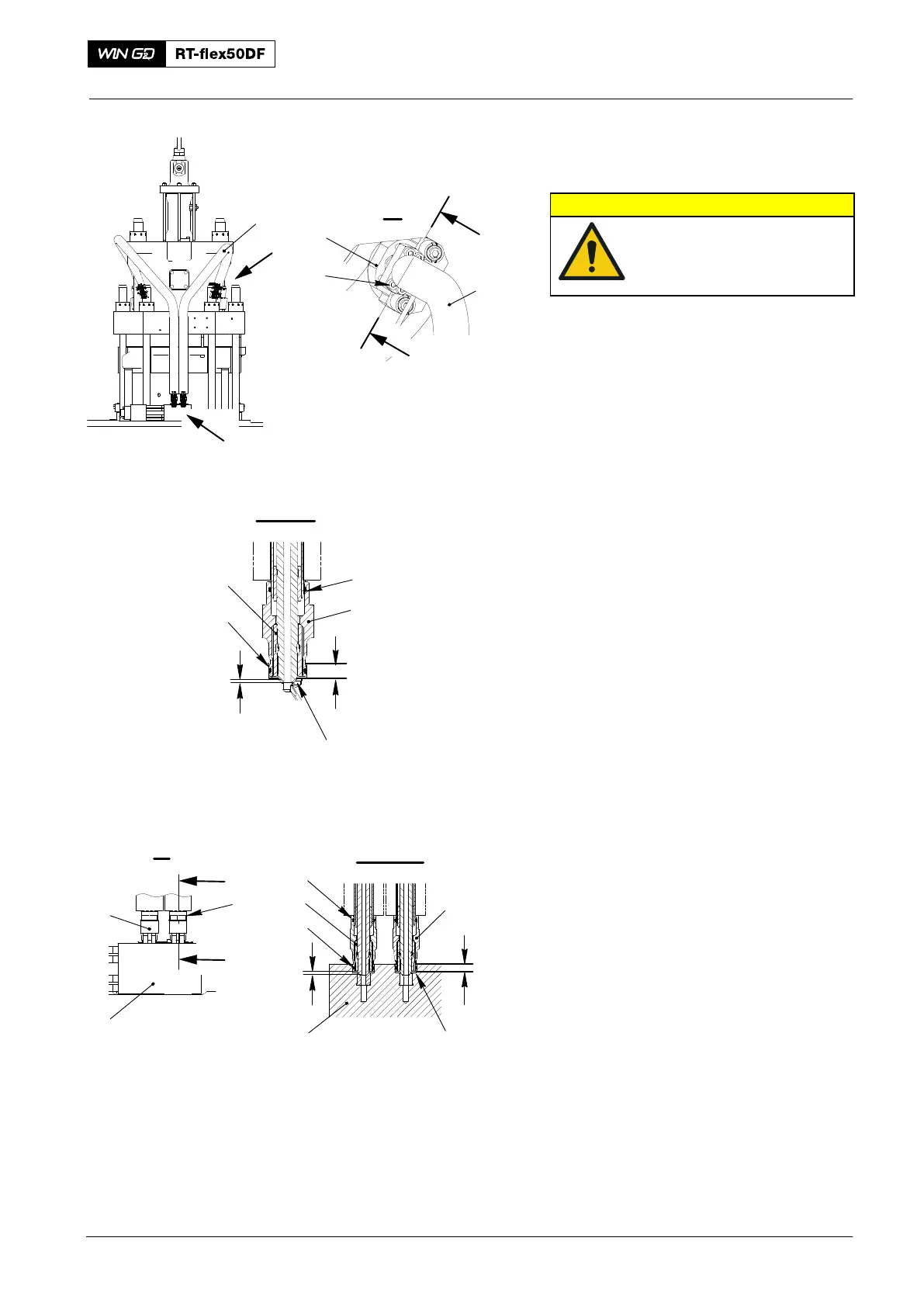
4. Installation
CAUTION
Damage Hazard: Make sure
that you do not damage
the sealing faces or the HP
injection pipes.
1) If necessary, attach the electrical trace
heating cable. To the HP injection pipe
(1, Fig. 3).
2) If necessary, replace the O-rings (4, 6,
10, 12).
3) Apply oil to the claws (7, 11), sealing
faces (SF) and to the ends of the
threads on the HP injection pipe (1).
4) Make sure that the claws (7, 11) are
correctly attached to the HP injection
pipe (1).
Note: Use only an open-ended wrench to
adjust the claws (7, 11).
5) Remove all of the protection from the
sealing faces in the injection valve (3)
and the flow limiting valve (9).
6) Make sure that there is a distance of
5.7 mm between the ends of the HP
injection pipe (1) and the claws (7, 11).
7) Apply Never-Seez NSBT8 to the
threads of the screws (2, 13).
8) Carefully put the HP injection pipe (1)
in position in the injection valve (3) and
the flow limiting valve (9).
9) Torque symmetrically the four
screws (2) to 40 Nm.
10) Make sure that there is a distance of
10.5 mm between the flange (14) and
the flow limiter valve (9).
11) Torque symmetrically the four screws
(13) to 40 Nm.
12) Make sure that there is a distance of
10.5 mm between the flange (7) and
the injection valve.
13) Install the insulation to the HP injection
pipe 1.
2016
HP Injection Pipe: Removal, Grind, Install
I
III
1
III
IV
IV
IV - IV
1
I
2
3
14
9
SF
SF
II
II
II - II
4
6
9
5.7 mm
10.5 mm
5.7 mm
10.5 mm
5
7
WCH02981
WCH02981
Fig. 3
8
10
12
11
13