Maintenance2708−1/A1
Winterthur Gas & Diesel Ltd.
4/ 5
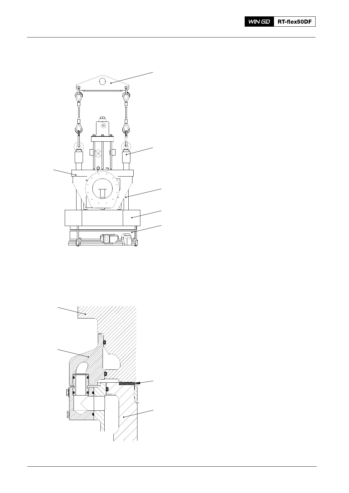
5. Cylinder cover −
Installation
1) Make sure that the compression space
is free from particles or dirt.
2) Make sure that the seating surfaces on
the cylinder cover (2, Fig. 3) and
cylinder liner (6) are clean and do not
have damage.
3) Put a new 2.0 mm soft iron joint ring (5)
in the cylinder liner (6). Make sure that
the joint ring is flat.
4) Clean the elastic studs of the cylinder
liner (6).
5) Apply Molykote paste G to the threads
of the elastic studs of the cylinder
liner (6).
6) Attach the special eye bolts (94265A)
to the elastic studs (1) on the exhaust
valve cage (4).
7) Attach the tool (94265) to the engine
room crane and the special eye
bolts (64265A).
8) Operate the engine room crane to lift
and move the cylinder cover (2)
(together with the exhaust valve cage
(4) and top water guide jacket (3)) into
position above the cylinder liner.
Note: During step 9), make sure that the
cylinder cover aligns correctly with
the elastic studs of the cylinder
liner (6).
9) Operate carefully the engine room
crane to lower the cylinder liner (2) on
to the cylinder liner (6).
10) Remove the tool (94265) and the
special eye bolts (94265A).
11) Attach the round nuts to the elastic
studs on the cylinder liner (6). Make
sure that the round nuts move freely.
12) Apply tension to the elastic studs, refer
to 2708−2.
13) For the configuration of the pre−tension
jacks, refer to 9403−2.
2016
Cylinder Cover and Water Guide Jacket − Removal and Installation
2
3
5
94265
94265A
1
2
3
4
012.895/05
Fig. 3
6