Maintenance
1224−1/A1
Winterthur Gas & Diesel Ltd.
1/ 6
Thrust Bearing Pads − Removal and Installation
Tools:
1 Turning-out device 94155 1 Turning-out device 94155A
(for 1-part gear wheel) (for 2-part gear wheel)
2 Spur-geared chain block (H1, H2) 94018−006 1 Eye bolt 94040−M12
1. Removal
1) Read the data in 0012−1 General Guidelines for Lifting Tools.
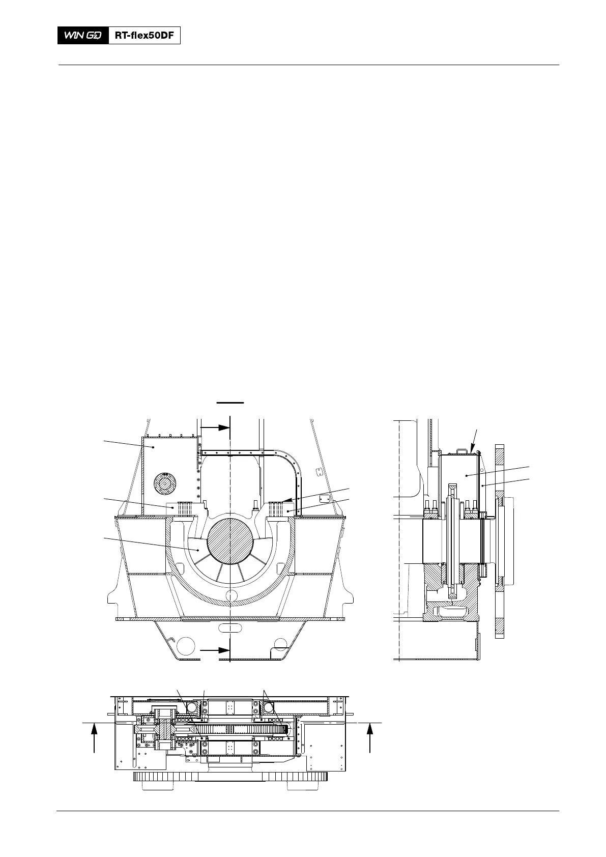
2) Remove the casing (8, Fig. 1) together with the oil baffle (top part) (9).
3) Attach the chain blocks (H1, H2, Fig. 2) to the attachment points in the gallery.
4) If necessary, remove the cover (7, Fig. 1) to get access to the arbor support (2).
5) Record the positions of the thrust bearing pads.
6) Remove the four bolts (1) from the applicable the arbor supports (2 or 5).
7) Attach the eye bolt (94040−M12) to the applicable arbor support (2 or 5).
8) Attach the chain block (H1 or H2) to the applicable arbor support (2 or 5).
9) Remove the applicable arbor support (2 or 5).
10) Do step 6) to step 9) for the other arbor supports.
I I
I - I
2
II
II
WCH00403
Fi
. 1
Note: For View II − II, see Fig. 2
1
2
5
6
3, 4
5
7
8
9
2
Thrust Bearing
2016