Maintenance
1203−1/A1
Winterthur Gas & Diesel Ltd.
1/ 2
Axial Clearance − Checks
Tools:
1 Inside micrometer 94101
1 Feeler gauge 94238
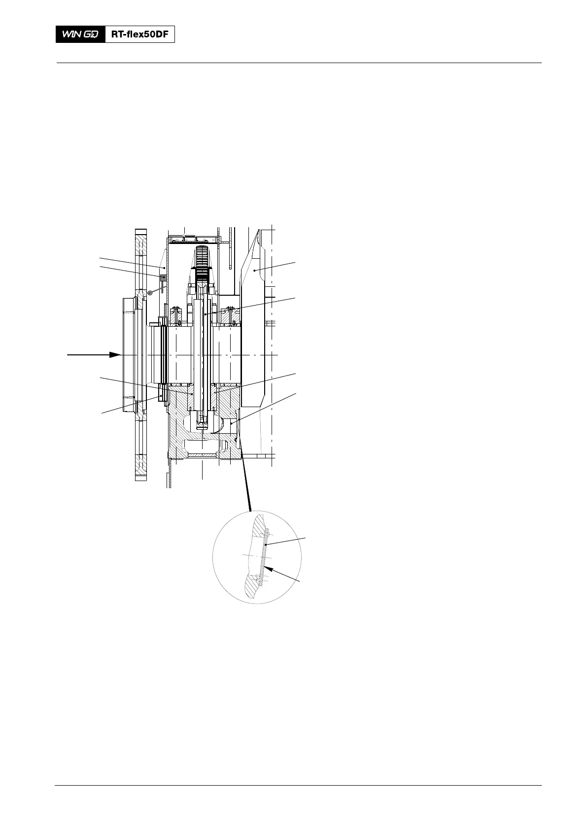
1. Procedure One
1) Start the engine in the direction AHEAD
to move the crankshaft fully forward.
2) Stop the engine.
3) Put the dial gauge (8, Fig. 1) in position
on the oil baffle (top part) (9) and
record the value.
4) Remove the dial gauge (8).
5) Start the engine in the direction
REVERSE to move the crankshaft fully
rearward.
6) Stop the engine.
7) Put the dial gauge (8) in position on the
oil baffle (top part) (9) and record the
value.
8) Remove the dial gauge (8).
9) Compare the values with those given in
the engine documents on the Check
Dimensions page (see also 0330−1
Clearance Table, Crankshaft and
Thrust Bearing).
If the measured values are more than the
nominal values given, the thrust pads are
worn.
10) After maintenance on the area of the
thrust bearing, do step a) to step d):
a) Remove the cover (4).
b) Do a check of the thrust bearing
housing.
c) If necessary, remove particles
from the area (11).
d) Install the cover (4).
11) Each 6000 to 8000 operation hours,
make sure that the opening (5) is clear.
2016
Thrust Bearing
THRUST
9
8
7
6
012.968/05
5
4
1
2
3
11
Fi
. 1