Maintenance
2722−1/A1
Winterthur Gas & Diesel Ltd.
3/ 4
3. Injection valve −
installation
WARNING
Injury and Damage Hazard:
Do not use copper paste in
this procedure. Copper
paste can be a conductor
of electricity. Injury to
personnel and damage to
equipment can occur.
1) Do a check of the condition of the
sealing face in the cylinder cover. If
necessary, grind the sealing face in the
cylinder cover, refer to 2708−3.
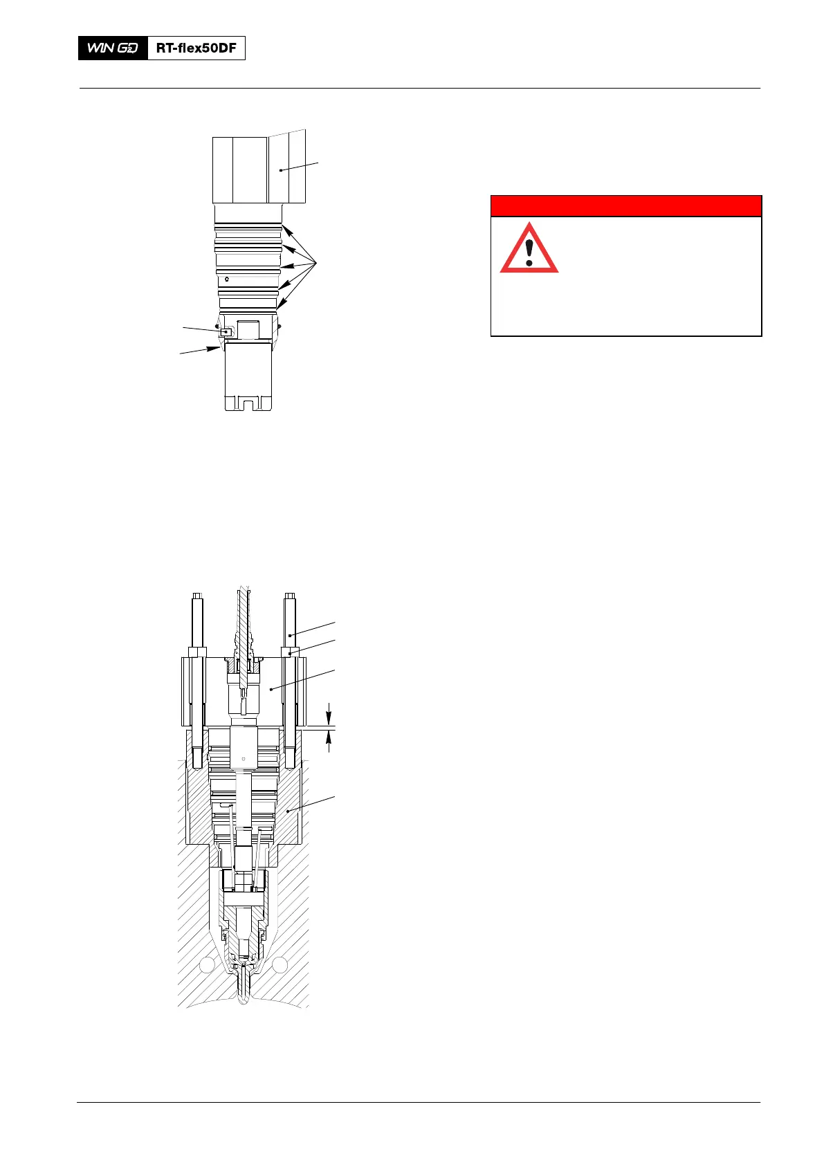
2) If necessary, remove the injection
valve (1, Fig. 3) from its package.
Note: The five O-rings (2) are part of the
spare parts set for the injection
valve.
3) Put the five new O-rings (2) in position
as follows:
a) Put the bush (94289C) in position
as shown.
b) Apply oil to the five O-rings.
c) Put the five O-ringsin their correct
positions.
d) Remove the bush (94289C).
4) Carefully put the the injection valve (1)
into the valve bush (5). The dowel pin
(3) makes sure that the injection valve
is in the correct position.
5) Put the two stud bolts (94270D) in
position as shown.
6) Turn equally the nuts (4) to push the
injection valve (1) fully in.
Note: The injection valve is fully
installed when the distance
between the valve bush (5) and the
injection valve (1) is 4.0 mm.
2018−02
Injection Valve: Removal and Installation
2
94289C
1
WCH00903
Fig. 3
WCH03113
94270D
1
5
4.0 mm
3
4