Maintenance
3403−1/A1
Winterthur Gas & Diesel Ltd.
1/ 9
Removal and Installation
Tools:
1 Working platform 94142 1 Spacer 94344A
2 Nuts 94142A 2 Chains 94344B
1 Support 94143 2 Distance holders 94345
1 Dismantling tool 94208 1 Piston supporting device 94350
1 Lifting hook 94209 1 Inserting cone 94342
2 Lifting bosses 94333A 1 Lifting tool 94341
1. Preparation 1.......................................................
2. Removal 2.........................................................
3. Installation 6.......................................................
4. Completion 9.......................................................
1. Preparation
WARNING
Injury Hazard: Before you
operate the turning gear,
make sure that no
personnel are near the
flywheel, or in the engine.
1) Read the data in 0012−1General
Guidelines for Lifting Tools.
2) Stop the engine, refer to the procedure
in the Operation Manual 4002−2.
3) Let the engine temperature decrease
before you start the removal procedure.
4) Make sure that all tools and equipment
are clean.
5) Remove the cylinder cover, refer to
2708−1.
6) Look at the area of the piston ring
stroke. If there is unwanted material,
refer to the procedure in 2124−3.
7) Clean the top part of the cylinder liner.
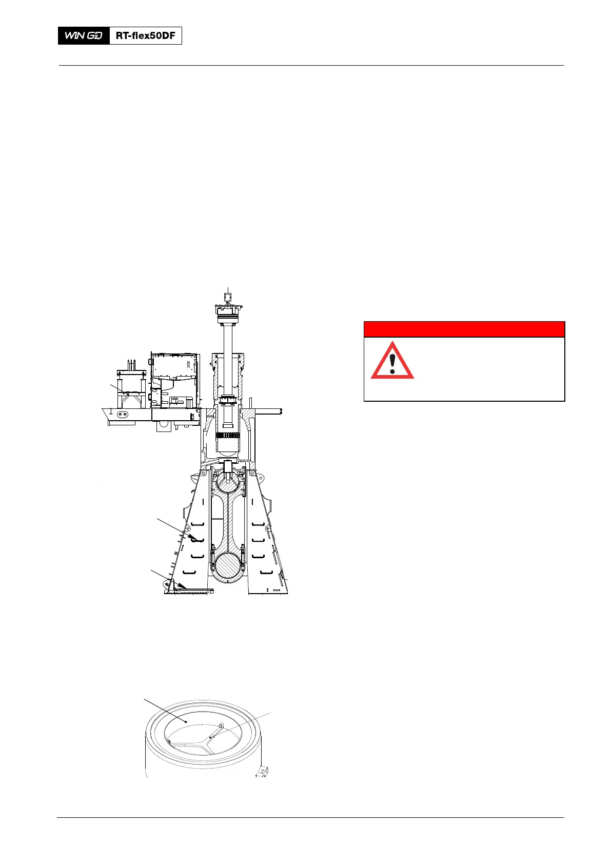
8) Install the piston supporting device
94350 on the gallery.
9) Install the work platform (94142) and
the support (94143), refer to 3301−1.
10) Attach the tool (94208, Fig. 2) to the
antipolishing ring (1) with the three
screws.
11) Attach applicable equipment to to the
engine room crane and the tool
(94208).
12) Operate the engine room crane to
remove the antipolishing ring (1).
2016
Piston
94350
94142
94143
WCH03299
Fig. 1
94208
Fig. 2
1