Maintenance3403−1/A1
Winterthur Gas & Diesel Ltd.
6/ 9
3. Installation
1) Make sure that the items that follow are
clean and in a satisfactory condition:
D All parts of the piston rod gland
D The piston ring grooves and the
piston rings
D All surfaces of the piston.
2) Make sure that the O-rings in the piston
rod gland are in a satisfactory
condition.
3) Apply oil to the bore and O-rings of the
piston rod gland.
4) Apply oil to the piston rings, piston skirt,
piston rod and running surface of the
cylinder liner.
5) Install the piston rings, refer to 3425−1.
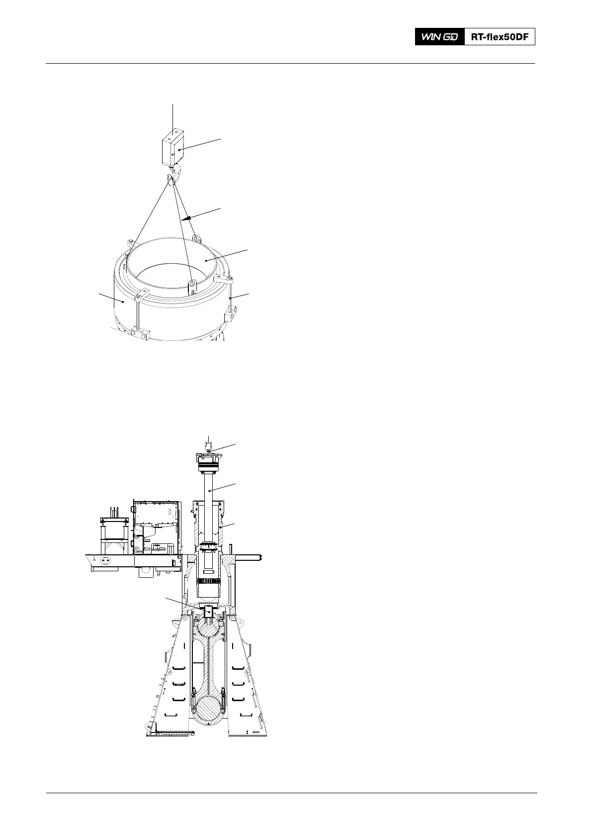
6) Put oil on the surfaces of the cone
(94342, Fig. 14).
7) Put oil on the bore and the O-rings of
the piston rod gland.
8) Make sure that the piston rod gland is
correctly installed on the piston rod.
9) Attach the sling (94209) to the engine
room crane.
10) Operate the crane to put the
tool (94342) in position on the cylinder
liner (3). Lock the tool in position with
the three bolts (2).
11) Make sure the distance holders (94345,
Fig. 7) are installed on the piston rod
foot (1).
12) Make sure that the spacer (94344A,
Fig. 15) is in position on the crosshead.
13) Attach the tool (94341) to the piston
crown, refer to step 17) to step 23)
above.
14) Attach the engine room crane to the
tool (94341).
15) Operate the turning gear to move the
crank to TDC.
16) On the piston support tool (94350)
loosen the screws (3, Fig. 12).
17) Turn and lock the two plates (2) up
before the piston touches them.
18) Lift the piston together with the piston
rod gland from the tool (9350)
19) Lift the piston together with piston rod
gland from the tool (94350).
20) Move the piston (1, Fig. 15) into
position above the cylinder liner (2).
Piston: Removal and Installation
2016
1
94209
94342
23
94344A
1
2
WCH03299
Fig. 14
Fig. 15
94341