Maintenance
3403−1/A1
Winterthur Gas & Diesel Ltd.
5/ 9
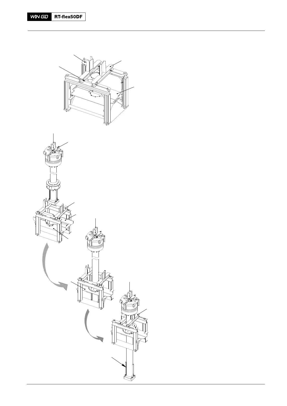
24) Make sure that the piston support
tool (94350, Fig. 12) is in the correct
position on the top platform.
25) Loosen the four screws (3).
26) Move fully out the two supports (1).
27) Lift and lock the plates (2) in the
vertical position.
28) Apply protection to the crosshead pin
and the top end bearing to prevent
damage and contamination.
29) Operate the crane to carefully lift the
piston from the cylinder. Make sure that
the piston rod foot does not touch the
support of the piston rod gland box.
30) Lower and align the piston between the
supports (1, Fig. 13) until the piston rod
foot is below the plates (2).
31) Close the plates (2).
32) Push fully in the two supports (1).
33) Tighten the four screws (3).
34) Lower the piston on to the supports (1).
35) Remove the crane hook from the
tool (94341).
36) Remove the distance holders (94230)
from the piston rod foot.
37) Remove the tool (94341).
38) To disassemble the piston, refer to
3403−3.
39) Do a check of the top surface of the
piston, refer to 3403−4.
40) Do a check of the piston rings and
grooves, refer to 3425−1.
41) Measure the bore of the cylinder liner,
refer to 2124−1.
42) If necessary, dress the lubricating
grooves and scavenge air ports, refer
to 2124−3.
43) Refer to the Maintenance Schedule for
other work on each piston 0380−1.
Select the related data.
Piston: Removal and Installation
2016
Fig. 12
WCH03082
Fig. 13
94350
1
3
2
94350
1
2
1
2
94341
94230
WCH03413