Maintenance
3303−4/A2
Winterthur Gas & Diesel Ltd.
1/ 6
Removal and Installation
Tools:
1 Work platform 94142 1 Lifting tool 94335
4 Retaining pins 94323 1 Stop plate 94370H
1 Lifting plate 94324 2 Manual ratchet 1600 kg H1, H2 94016−007
2 Lifting rings 94332 2 Manual ratchet 3200 kg H3, H4 94016−013
1 Spur-geared chain block 2000 kg H5 94017−022 3 Eye bolts M8 EB1, EB2, EB3 94040−M8
1 Holder 94331
1. General 1..........................................................
2. Preparation 1.......................................................
3. Removal 1.........................................................
4. Installation 4.......................................................
5. Completion 6.......................................................
1. General
WARNING
Injury Hazard: Before you
operate the turning gear,
make sure that no
personnel are near the
flywheel, or in the engine.
WARNING
Injury Hazard: The
connecting rod weighs
1142 kg. To prevent injury,
be careful when you move
the connecting rod.
2. Preparation
1) Read the data in 0012−1 General
Guidelines for Lifting Tools.
2) Remove the bottom end bearing cover,
refer to 3303−2.
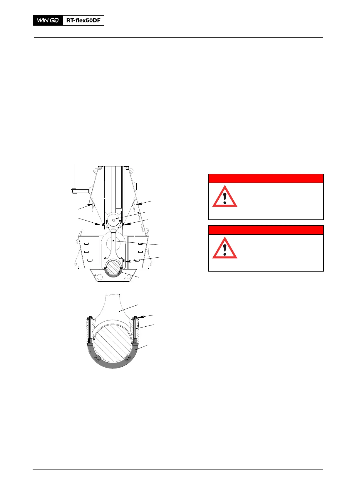
Note: If the piston is installed, refer to
3303−2, paragraph 2.1 to lift the
crosshead (1, Fig. 1).
Note: If the piston is removed, refer to
3303−3, paragraph 2.2 to lift the
crosshead (1).
3) Attach the holder (94331) to the
connecting rod (2) with the nuts(3).
4) Attach the two eye bolts (EB1, EB2) to the connecting rod (2).
5) Attach the manual ratchets (H1, H2) to the attachment points in the column.
6) Operate the manual ratchets (H1, H2) to apply a light tension to the chains.
3. Removal
1) Operate the turning gear to turn the crank of the applicable cylinder to BDC. At
the same time, operate the manual ratchets (H1, H2) to keep a light tension on
the chains.
2016
Connecting Rod
94331
2
H2
H1
EB1
013.020/05
2
94331
Fig. 1
1
4
3
EB2
EB3