Maintenance3303−4/A2
Winterthur Gas & Diesel Ltd.
2/ 6
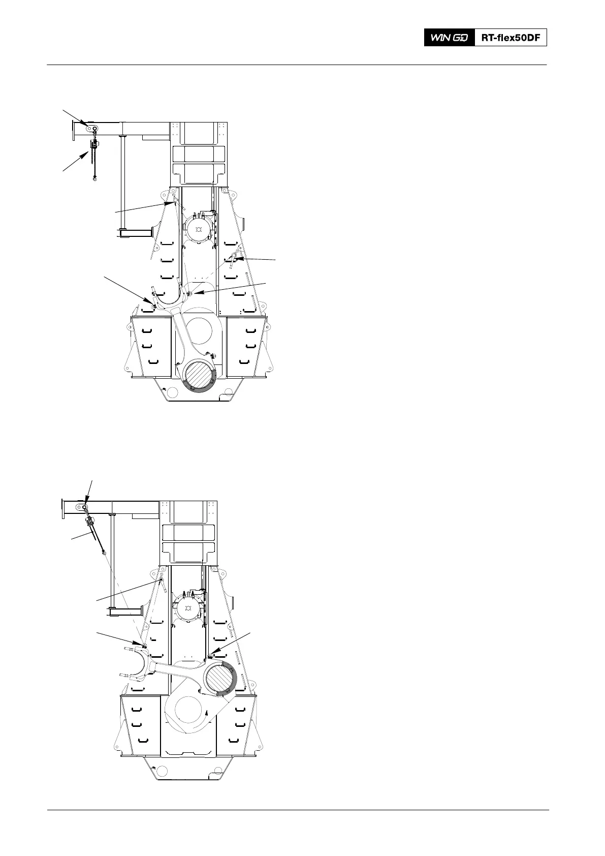
2) Attach the lifting tool (94335, Fig. 2).
between reinforced double-I girders,
refer to 3301−2.
3) Attach the chain block (H5) to the lifting
tool (94335).
4) Operate the manual ratchets (H1, H2)
to move the connecting rod to the fuel
side.
5) Remove the manual ratchet (H1) from
the bottom attachment point and the
eye bolt (EB1).
6) Attach the manual ratchet (H1) to the
top attachment point in the column and
the eye bolt (EB2).
7) Remove the manual ratchet (H2).
8) Remove the eye bolt (EB1).
9) Operate the turning gear to move the
crank counterclockwise approximately
45° . At the same time, operate the
manual ratchet (H1, Fig. 3) to get the
connecting rod through the column
door.
10) Remove the applicable bottom plates
from the middle platform.
11) Attach the chain block (H5) to the eye
bolt (EB2).
12) Remove the manual ratchet (H1) from
the eye bolt (EB2).
13) Attach the eye bolt (EB3) to the
connecting rod as shown.
2016
Connecting Rod: Removal and Installation
Fig. 2
H1
H2
H5
94335
013.036/05a
94335
H5
Fig. 3
H1
EB2
EB3
EB1
EB2