Maintenance
3303−4/A2
Winterthur Gas & Diesel Ltd.
5/ 6
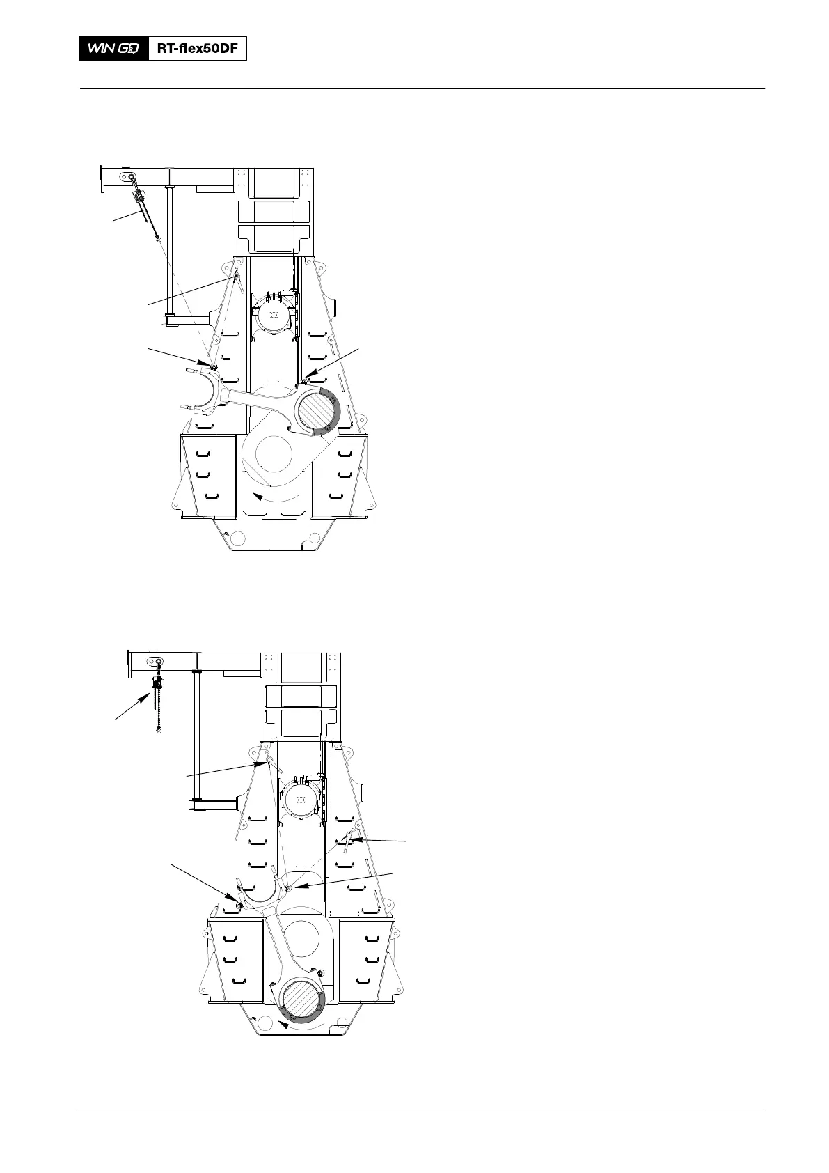
8) Operate the turning gear to move the
crank clockwise. At the same time,
operate the chain block (H5, Fig. 8) to
hold the connecting block.
9) Attach the manual ratchet (H1) to the
eye bolt (EB 2).
10) Remove the manual ratchet from the
eye bolt (EB3).
11) Remove the chain block (H5) from the
eye bolt (EB2).
12) Operate the turning gear to move the
crank clockwise.
13) Attach the manual ratchet (H2, Fig. 9)
to the eye bolt (EB2).
14) Remove the manual ratchet (H1) from
the eye bolt (EB2).
15) Remove the manual ratchet (H1) from
the the top attachment point in the
column.
2016
Connecting Rod: Removal and Installation
Fig. 8
013.036/05a
H5
Fig. 9
H1
EB2
EB3
H1
H2
H5
EB1
EB2
013.036/05a