Maintenance
3303−2/A2
Winterthur Gas & Diesel Ltd.
1/ 7
Bottom End Bearing − Removal, Inspection and
Installation
Tools:
1 Work platform 94142 1 Spur-geared chain block H3 94017−022
4 Retaining pins 94323 2 RUD-eye bolt M8 94040−M8
1 Lifting tool 94335 2 Manual ratchets 1600 kg H1, H2 94016−007
1 Chain (double sling) 94666I 2 Swivel lugs 94048−M30
2 Eye bolts M6 94040−M6 2 Swivel lugs 94048−M30
1. General 1..........................................................
2. Preparation 1.......................................................
3. Bearing Cover − Removal 1.........................................
4. Bottom Bearing Shell − Removal 3...................................
5. Top Bearing Shell − Removal 3......................................
6. Inspection 4........................................................
7. Top Bearing Shell − Installation 4....................................
8. Bottom Bearing Shell − Installation 5.................................
9. Bearing Cover − Installation 5.......................................
1. General
WARNING
Injury Hazard: Before you operate the turning gear, make sure
that no personnel are near the flywheel, or in the engine.
2. Preparation
1) Operate the turning gear to turn the
crankshaft until the applicable crank is
at TDC.
2) Lock the turning gear.
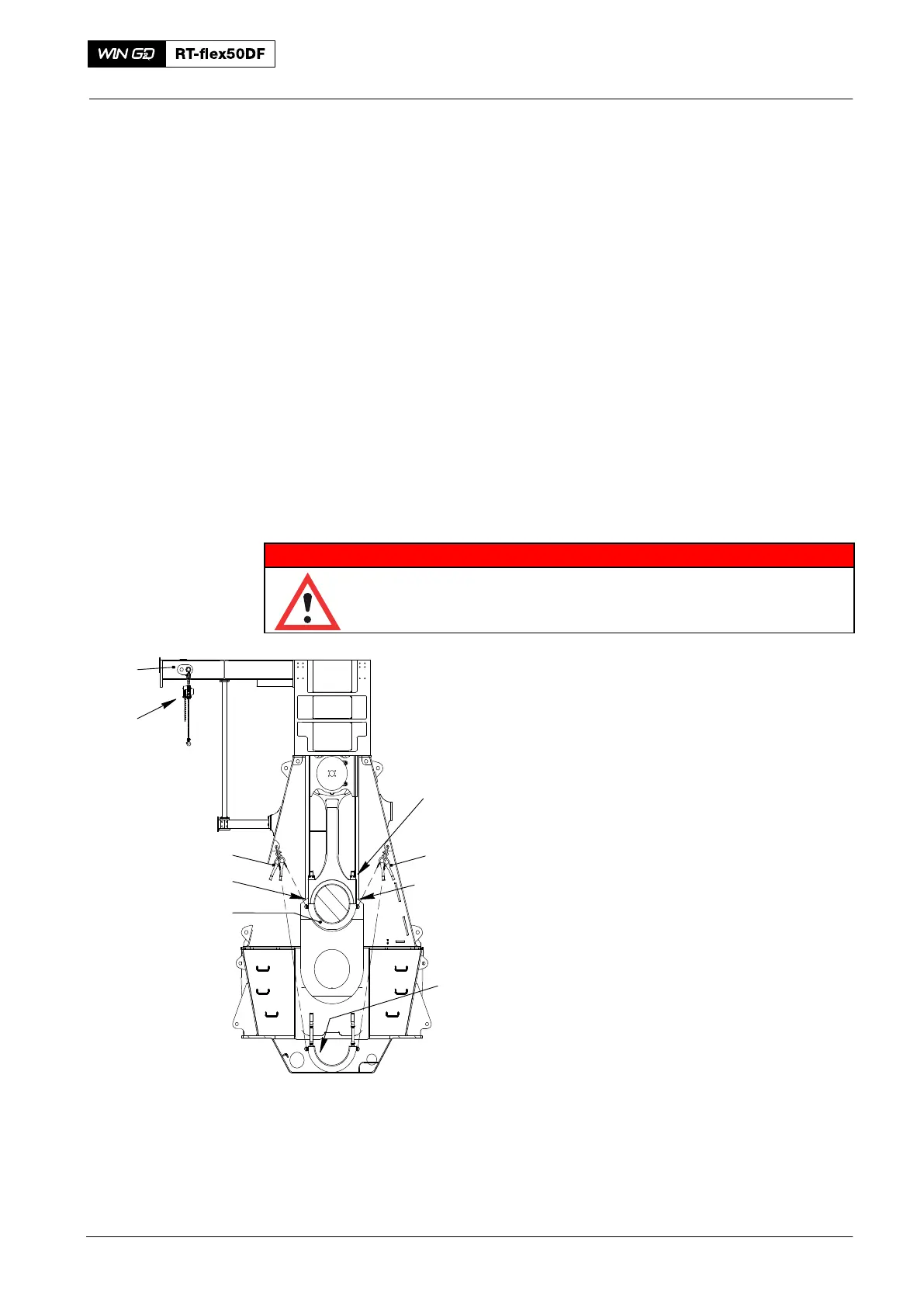
3) Attach the swivel lugs (94048−M30,
Fig.1) to the bearing cover (3).
4) Attach the manual ratchets (H1, H2) to
the column and the eye
bolts (94040−M8) on the bearing
cover (3).
5) Attach the lifting tool (94335) between
double-I girders.
6) Attach the chain block (H3) to the lifting
tool (94335).
3. Bearing Cover −
Removal
1) Loosen then remove the round nuts (1),
refer to 9403−4.
2) Operate the manual ratchets (H1, H2) to carefully lower the bearing cover (3).
Make sure that you do not cause damage to the threads of the elastic studs and
the surface of the crank pin.
3) Do an inspection of the bearing shell (2).
4) If the bearing shell (2) is in good condition, lower bearing cover (3) to the bottom
of the crankcase.
2016
Connecting Rod
H2
H1
94048−M30
013.502/05a
Fig. 1
2
H3
94335
94048−M30
3
1