Maintenance
3303−2/A2
Winterthur Gas & Diesel Ltd.
5/ 7
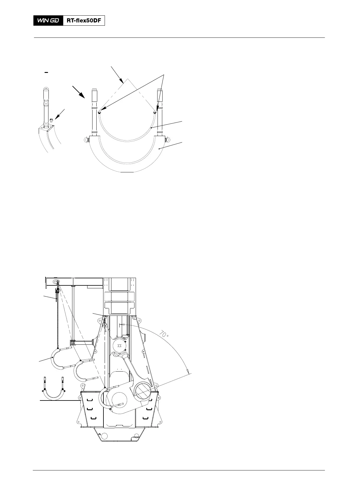
8. Bottom Bearing Shell −
Installation
1) Attach the two eye bolts (94040−M6,
Fig. 7) to the bottom bearing shell (1).
2) Attach the chain (94666I) to the two
eye bolts (94040−M30) and the chain
block (H3).
3) Lift the bottom bearing shell (1).
4) Clean the seating surfaces of the
bottom bearing shell (1) and the
bearing cover (2).
5) Put oil on the surface of the bearing
shell (1).
6) Lower the bearing shell (1) on to the
bearing cover (2).
Note: Make sure that the distance
between each end of the bearing
shell and the connecting rod is the
same.
7) Remove the chain (94333I).
8) Remove the two eye bolts (94040−M6).
9) Attach the bottom bearing shell (1) to
the bearing cover (2) with the two
screws (3).
9. Bearing Cover −
Installation
1) Attach the chain block (H3) to the eye
bolt on bearing cover (1, Fig. 8).
2) Attach the manual ratchet (H1) to the
top attachment point in the column and
the eye bolt on the bearing cover (1).
3) Operate the turning gear to move the
crankshaft to the position shown.
4) Operate the manual ratchet (H1) and
the chain block (H3) to move the
bearing cover through the column door
as shown.
2016
Bottom End Bearing − Removal, Inspection and Installation
1
2
I
3
I
013.507/05
94040−M6
94666I
Fig. 7
H3
013.506/05a
1
Fig. 8
H1