Maintenance3303−2/A2
Winterthur Gas & Diesel Ltd.
6/ 7
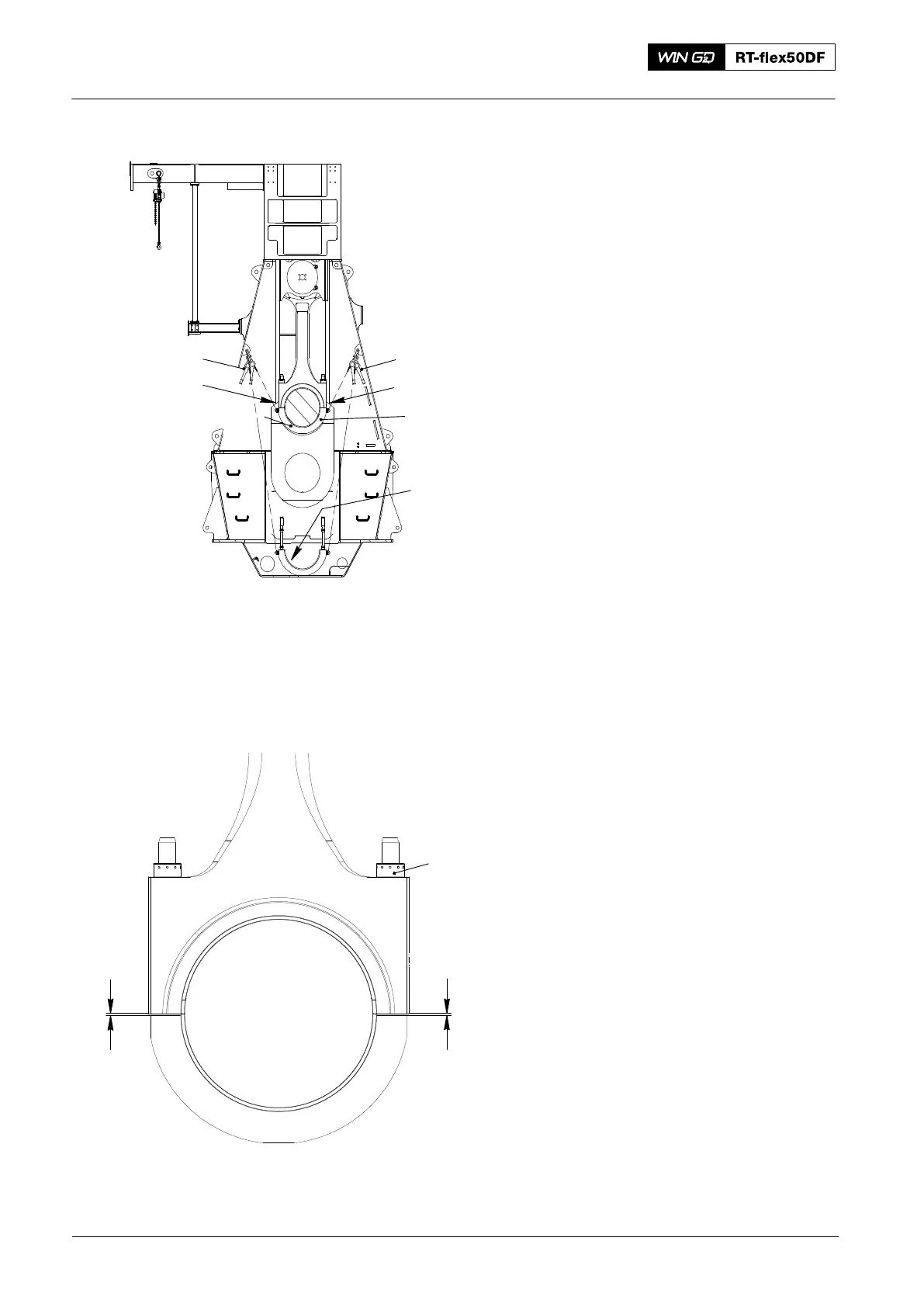
5) Attach the manual ratchet (H2, Fig. 9)
to the attachment point in the column
and the eye bolt (94040−M8).
6) Attach the manual ratchet (H1) to the
bottom attachment point in the column
and the eye bolt (94040−M8).
7) Carefully remove the chain block (H3).
8) Make sure that the bearing shell (2) is
clean.
9) Operate the manual ratchets (H1, H2)
to lift the bearing cover (1) into position.
10) Put oil on the bearing shell as follows:
a) If you start the engine immediately
after completion of this procedure,
use only bearing oil.
b) If the engine has stopped for
some days, use a mixture of
high-viscosity oil (steam engine
cylinder oil, ISO VG 1000/1500)
and bearing oil. The ratio is two
thirds ISO VG 1000/1500 to one
third bearing oil.
Note: A list of suppliers for ISO VG
1000/1500 high viscosity oils is
given in Table 1.
11) Put the round nuts (1, Fig. 10) on the
elastic studs.
12) Tighten the round nuts (1) equally with
a round bar.
13) Measure the distances (X1, X2)
between the edges of the bearing
shells and the bearing cover.
14) Refer to 0330−1 Group 3303 to get the
clearance values (X1, X2) for new
bearing shells.
15) Apply tension to the elastic studs, refer
to 9403−4.
16) Remove all tools and equipment from
the area.
2016
Bottom End Bearing − Removal, Inspection and Installation
H2
H1
94040−M8
013.502/05a
94040−M8
Fig. 9
Fig. 10
x
2
x
1
2
1
013.540/05
1