Maintenance
3303−3/A2
Winterthur Gas & Diesel Ltd.
1/ 10
Top End Bearing − Removal, Inspection and Installation
Tools:
1 Work platform 94142 1 Lifting tool 94335
4 Retaining pins 94323 1 Stop plate 94370H
1 Lifting plate 94324 2 Manual ratchet 1600 kg H1, H2 94016−007
2 Lifting rings 94332 2 Manual ratchet 3200 kg H3, H4 94016−013
1 Spur-geared chain block 2000 kg H5 94017−022 4 RUD-eye bolts M8 94040−M8
2 Chain 94666I 2 Eye bolts M6 94040−M6
1. General 1..........................................................
2. Bearing Shell − Removal 1..........................................
2.1 Crosshead − Lift (Installed Piston) 2............................
2.2 Crosshead − Lift (Piston Removed) 4...........................
3. Bearing Shell − Removal 5..........................................
4. Inspection 5........................................................
5. Bearing Shell − Installation 6........................................
5.1 Installation with Piston Installed 6..............................
5.2 Installation with Piston Removed 8.............................
1. General
WARNING
Injury Hazard: Before you operate the turning gear, make sure
that no personnel are near the flywheel, or in the engine.
2. Bearing Shell −
Removal
Note: You can examine the bearing shell
with piston installed or removed.
1) Read and obey the data in 0012−1
General Guidelines for Lifting Tools.
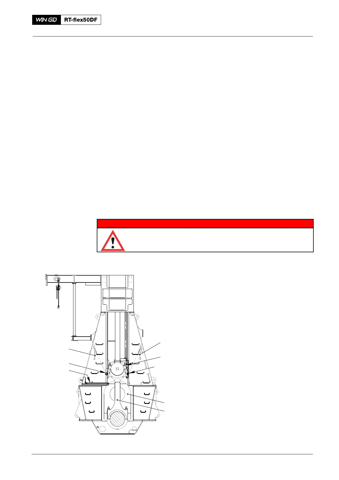
1) Operate the turning gear to move the
crank (2, Fig. 1) of the applicable
cylinder to BDC.
2) Install the work platform (94142) refer
to 3301−1.
3) Attach the eye bolts (94040−M8) to
each side of the connecting rod (3).
4) Attach the manual ratchets (H1, H2) to
the attachment points in the column
and the eye bolts (94040−M8).
2016
Connecting Rod
94142
013.626/05a
H1
94040−M8
H2
1
3
2
Fig. 1
94040−M8