Maintenance
3303−3/A2
Winterthur Gas & Diesel Ltd.
5/ 10
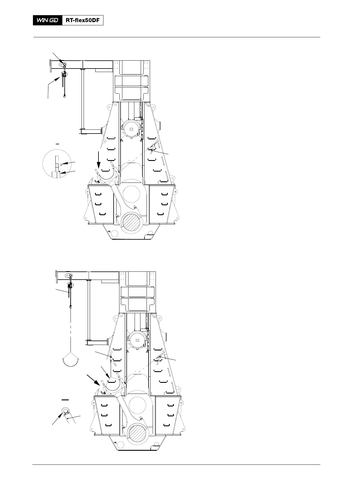
3. Bearing Shell −
Removal
1) Attach the lifting tool (94335, Fig. 5)
between the double-I girders.
2) Operate the manual ratchets (H1, H2)
to move the connecting rod a small
distance to the fuel side.
3) Remove the manual ratchet (H1) from
the swivel lug (94048−M30) on the
connecting rod. Make sure that the
connecting rod stays on the fuel side.
4) Operate the manual ratchet (H2) to
move the connecting rod fully to the
fuel side.
5) Remove the Allen screws (10) from the
bearing shell (11).
6) Attach the two eye bolts (94040−M6) to
the bearing shell.
7) Attach the chain (94666I) to the eye
bolts (94040−M6) and the manual
ratchet (H1).
8) Apply protection to the threads of the
elastic studs on the connecting rod.
This prevents damage to the bearing
shell.
9) Operate the manual ratchet (H1) to
carefully lift the bearing shell a small
distance.
10) Attach the chain block (H5) to the
chain (94666I).
11) Remove the manual ratchet (H1) from
the sling (94666I).
12) Carefully operate the chain block to
move the bearing shell through the
column door.
13) Lower the bearing shell on to the
platform.
4. Inspection
1) Do an inspection of the bearing shell.
2) If you find damage, replace the bearing
shell.
2016
Top End Bearing − Removal, Inspection and Installation
1
013.632/05a
2
I
I
H2
013.637/05a
H5
94335
H1
Fig. 5
Fig. 6
94017−022
I
I
H2
94040−M6
94666I
1