Maintenance3303−3/A2
Winterthur Gas & Diesel Ltd.
6/ 10
5. Bearing Shell − Installation
5.1 Installation with Piston Installed
1) Clean the seating surface of the bearing shell (1, Fig. 7).
2) Put oil on the surface of the bearing shell (1) as follows:
a) If you start the engine immediately after completion of this procedure, use only
bearing oil.
b) If the engine has stopped for some days, use a mixture of high-viscosity oil
(steam engine cylinder oil, ISO VG 1000/1500) and bearing oil. The ratio is two
thirds ISO VG 1000/1500 to one third bearing oil.
Note: A list of suppliers for ISO VG 1000/1500 high viscosity oils is given in
Table 1.
3) Clean the seating surface of the connecting rod and make sure that there is no
damage.
4) Make sure that the surface of crosshead pin is in a satisfactory condition.
5) Install the eye bolts (94040−M6) to the bearing shell.
6) Attach the chain (94666I) to the manual ratchet (H5) and the eye bolts
(94040−M6).
7) Operate the chain block (H5) to lift the bearing shell (1) to the height of the
column door.
8) Attach the manual ratchet (H1) to the chain (94666I).
9) Operate the chain block (H5 and the
manual ratchet (H1) to carefully lower
the bearing shell (1) into the connecting
rod.
10) Install the two screw screws (2, Fig. 5).
Note: Make sure that the distance
between each end of the bearing
shell and the connecting rod is the
same.
11) Remove the four eye bolts (94040−M6,
Fig. 7).
12) Remove the protection from the elastic
studs on the connecting rod.
13) Remove the chain block (H5) and the
chain (94666I).
14) Attach the manual ratchet (H2) to the
eye bolts (94040−M8).
15) Operate the manual ratchet (H2) to
move the connecting rod a small
distance.
16) Attach the manual ratchet (H1) to the
eye bolt (94040−M8) on the connecting
rod.
17) Operate the manual ratchets (H1, H2)
to move the connecting rod to the
vertical position.
2016
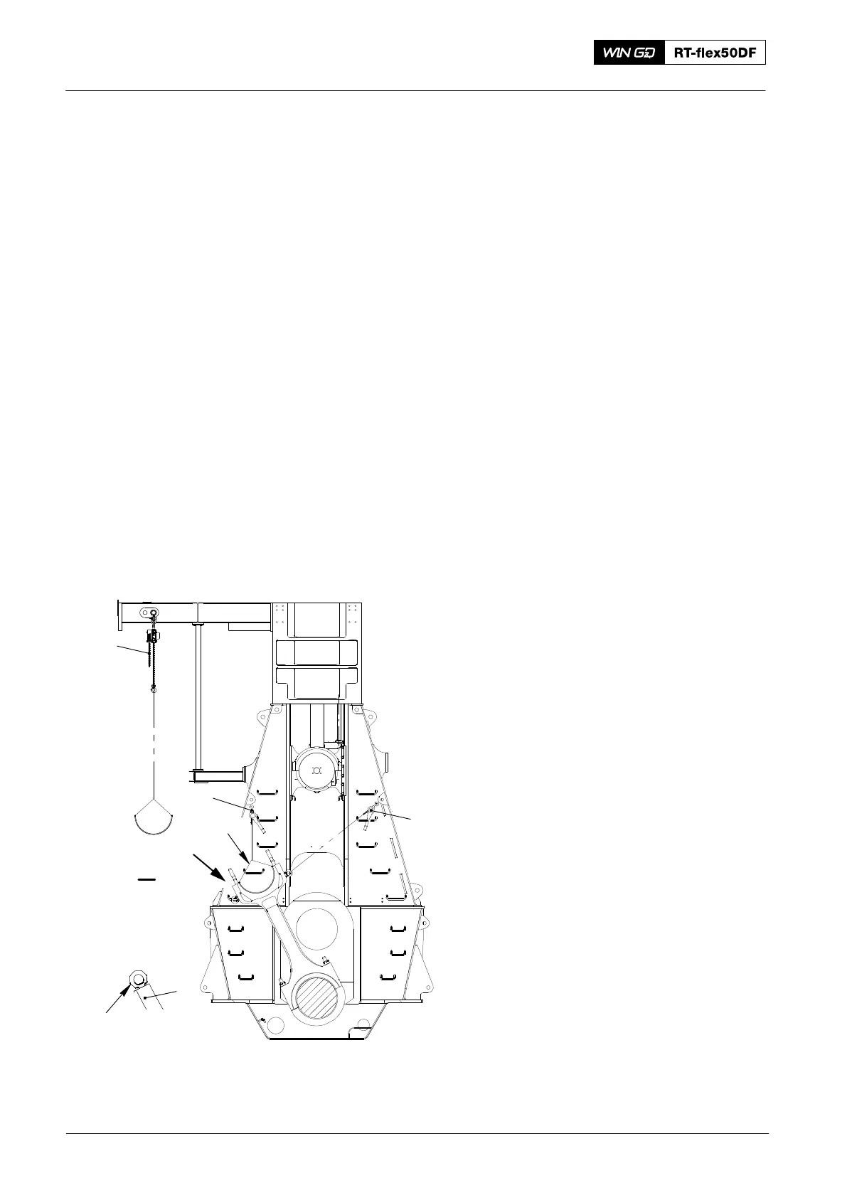
Top End Bearing − Removal, Inspection and Installation
Fig. 7
013.637/05a
H5
H1
I
I
H2
94040−M6
94666I
1