Maintenance5556−1/A1
Winterthur Gas & Diesel Ltd.
10/ 13
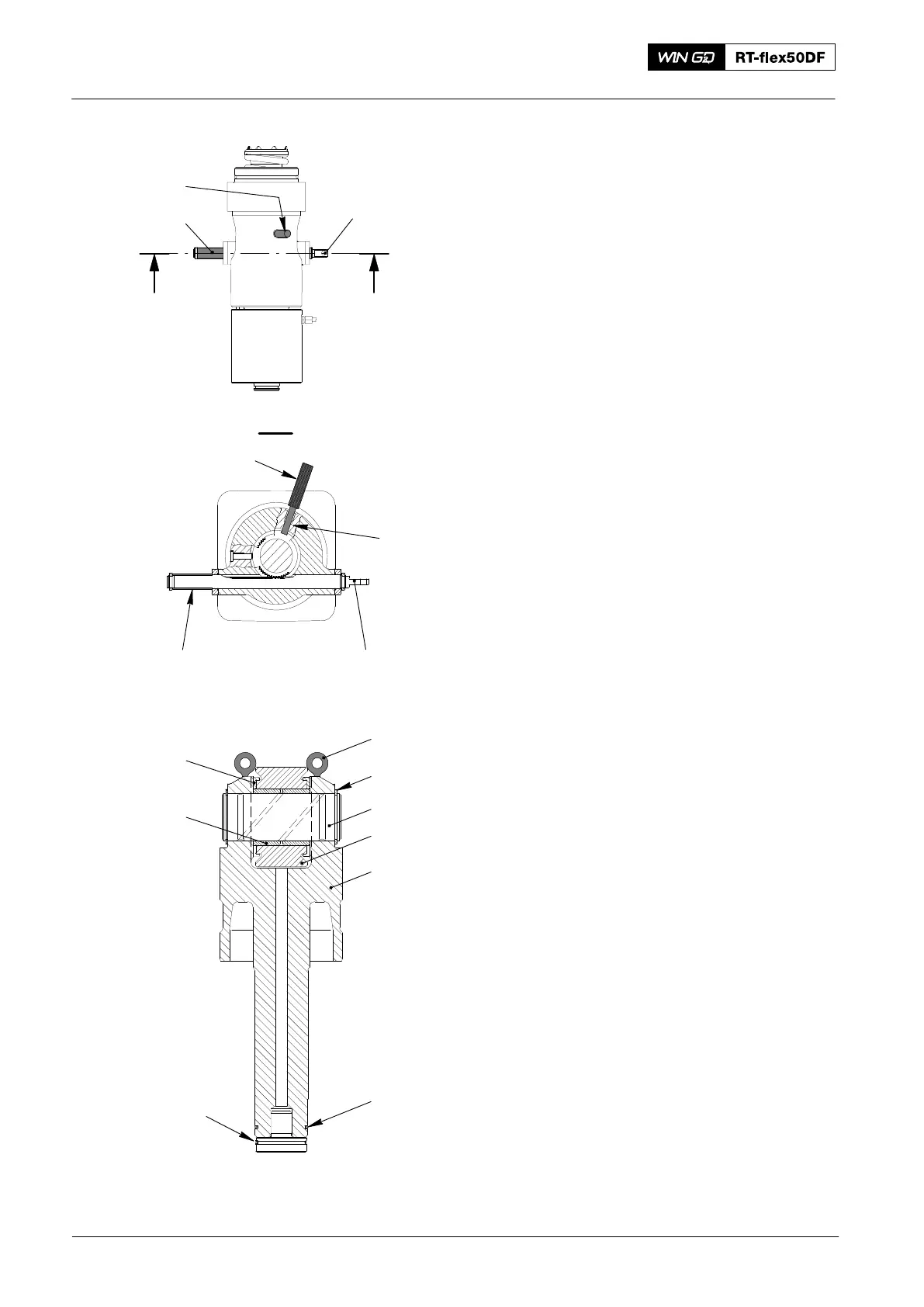
4.7 Plunger Position − Check
1) Move the toothed rack (1, Fig. 16) to
the position shown.
2) Put the spacer (94555) in the position
shown.
3) Remove the screw plug (not shown)
from the check bore (2).
4) Install fully the gauge (94556) into the
check bore (2).
5) Remove the spacer (94555).
6) Make sure the toothed rack (1) cannot
move. If the toothed rack cannot move,
the pump plunger is correctly installed.
7) Remove the gauge (94556).
8) Put copper paste on the thread of the
screw plug.
9) Install the screw plug to the check
bore (2).
10) Lubricate the new O-ring (6, Fig. 16).
11) Put the new O-ring (6) on the guide
piston (4).
12) Put grease on the snap ring (5).
13) Attach the snap ring (5) to the guide
piston (4).
14) Lubricate the pump plunger.
15) Install the bush (6), pressure discs (7)
and the roller (3) to the guide bush (4).
16) Install the pin (2) and the circlip (1).
17) Put the guide piston (4) in the housing.
18) Do a check of the axial clearances,
refer to 0330−1 Fuel pump.
19) Attach the two eye bolts (EB) to the
guide piston (4).
20) Attach the applicable lifting tools to the
eye bolts (EB).
Fuel Pump: Removal, Disassemble, Assemble, Installation
2016
I I
I - I
94556
94555 1
94555
008.657/00
008.658/00
94556
1
Fig. 16
2
Fig. 17
EB
008.649/00
2
4
1
3
5
7
8
6