Maintenance
3303−2/A2
Winterthur Gas & Diesel Ltd.
3/ 7
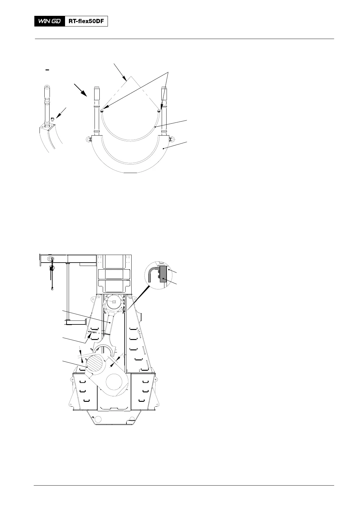
4. Bottom Bearing Shell −
Removal
1) Remove the two Allen screws (3,
Fig. 3).
2) Attach the two eye bolts (94040−M6) to
the bearing shell.
3) Attach the chain (94666I) to the eye
bolts (94040−M30).
4) Attach the chain block (H3) to the
chain (94666I).
5) Operate the chain block (H3) to lift the
bearing shell (1) from the bearing
cover (2).
5. Top Bearing Shell −
Removal
1) Unlock the turning gear.
2) Operate the turning gear to move the
crank to TDC.
3) Put the four retaining pins (94323,
Fig. 4) into the bores of guideways (1).
4) Operate the turning gear to carefully
turn the crankshaft to the fuel side until
the guide shoes touch the retaining
pins (94323). Make sure that the guide
shoes touch equally the retaining pins.
If necessary, adjust the retaining pins.
5) Attach the manual ratchet (H1) to the
column and the connecting rod.
6) Operate the manual ratchet (H1) to
hold the connecting rod in the position
shown.
7) Operate the turning gear to move the
crankshaft to the fuel side. At the same
time, operate the manual ratchet (H1)
to keep a light tension on the chain.
8) Continue to operate the turning gear
until the distances at X between the
crankshaft and the bottom end bearing
are equal.
2016
Bottom End Bearing − Removal, Inspection and Installation
Fig. 3
1
2
I
3
I
013.507/05
94040−M6
94666I
013536/05a
H1
1
94323
X
X
Fig. 4
3
2