Maintenance3403−1/A1
Winterthur Gas & Diesel Ltd.
2/ 9
2. Removal
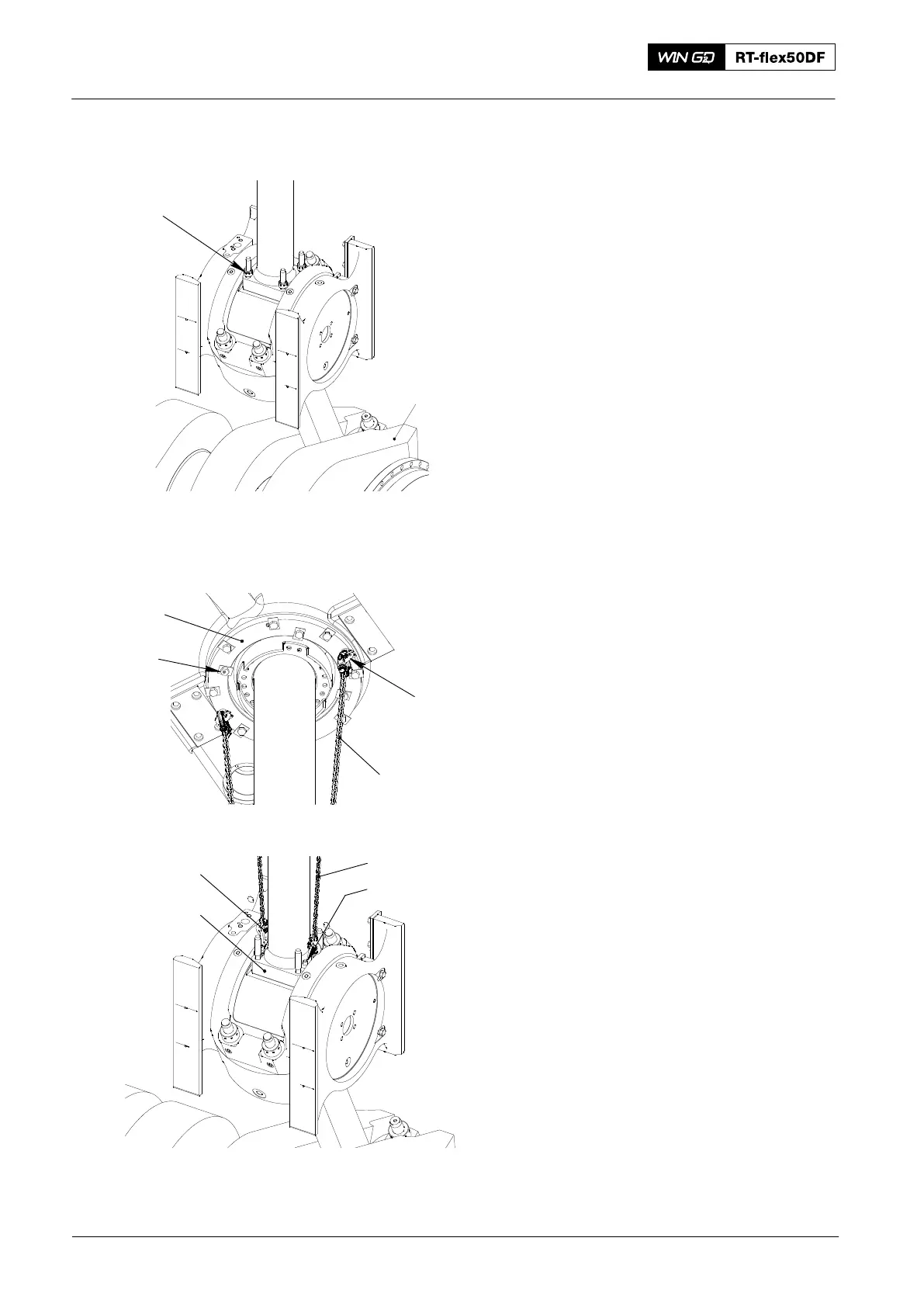
1) Remove the work platform (94142) and
the support (94143).
2) Operate the turning gear to move the
crank (1, Fig. 3) approximately 90° to
BDC.
3) Remove the four round nuts (2, Fig. 3)
from the piston rod foot (1), refer to
9403−4.
4) Remove the four inner bolts (5, Fig. 4)
from the support (6). Do not remove the
support (6).
5) Attach the two eye bolts (EB) to the
support (6).
6) Attach the lifting bosses (94333A) to
the piston rod foot (4) with the Allen
screws (3).
7) Attach the two suspension chains
(94344B) to the eye bolts (EB) and the
lifting bosses (94333A).
Note: When you do step 8), make sure
that the bolts of the piston rod foot
do not catch.
8) Operate the turning gear to move the
crank to BDC until the chains are tight.
Piston: Removal and Installation
2016
Fig. 3
WCH00082
5
6
EB
94344B
Fig. 4
1
2
94333A
94344B
3
4