Maintenance1132−2/A1
Winterthur Gas & Diesel Ltd.
14/ 14
6.2 Main Bearing Cover −
Installation
1) Make sure that the work area and all
tools and equipment are clean and in
good condition.
2) Use the applicable equipment to get
the bearing cover in the correct position
above the crankshaft as follows:
D For bearing covers No. 2 to No. 8
refer to paragraph 2.
D For bearing cover No. 1, refer to
paragraph 3).
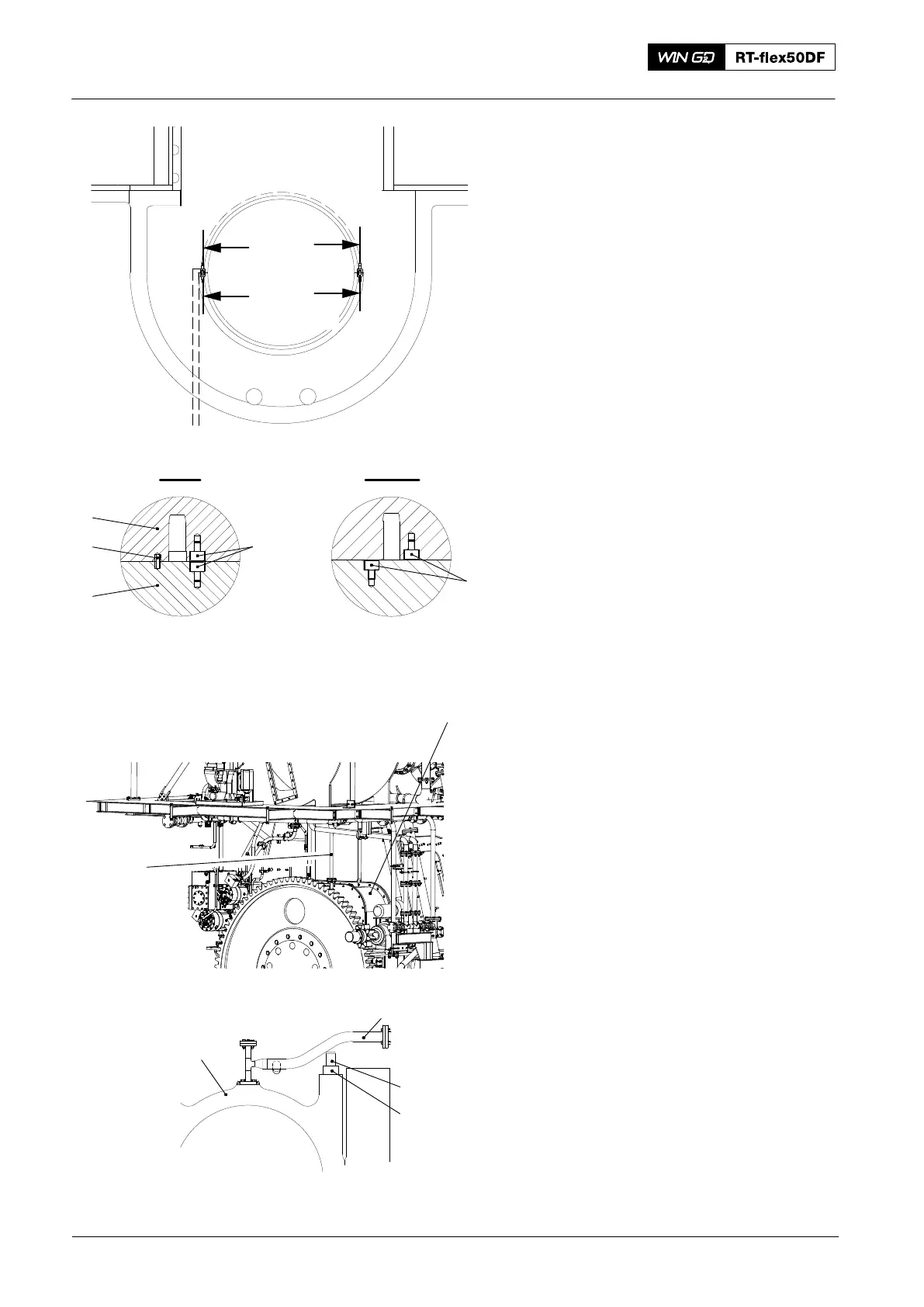
3) Attach the Allen screws (1, Fig. 17) to
bearing girder (2) on the fuel side.
4) Clean all surfaces of the bearing cover
and the bearing girder.
5) Lower the bearing cover on to the
bearing girder. Make sure that the two
spring dowels (3) engage correctly.
6) Apply tension to the elastic studs (3,
Fig. 18), refer to 1132−1.
7) Tighten the round nuts (4).
8) Remove the protection from the oil
bores.
9) Clean the pipe (2).
10) Install the pipe (2) to the bearing
cover (5).
11) Do step a) and step b) if the cover (1)
was removed.
a) Install the cover (1).
b) Install the pipe (6).
12) Remove all tools and equipment from
the work area.
13) Measure the bearing clearance and
compare the value measured in
paragraph 2, step 4) with the value
given in the clearance table 0330−1.
Note: If the clearance is in the limits
given, the bearing can be removed
and installed again.
14) After each installation of a new bearing
shell, measure the crank deflection,
refer to 3103−1.
15) Set to on the main oil supply pump.
16) Do a check of the oil supply to the main
bearing.
Main Bearing − Removal and Installation
2016
Fig. 17
I
I
II
II
018.677/09
I - I
3
4
1
2
II - II
1
Fig. 18
2
5
3
4
VIEW ON FLYWHEEL
FROM AFT END
1
6
WCH02325
Note: Some parts can look different