Maintenance
3303−3/A2
Winterthur Gas & Diesel Ltd.
9/ 10
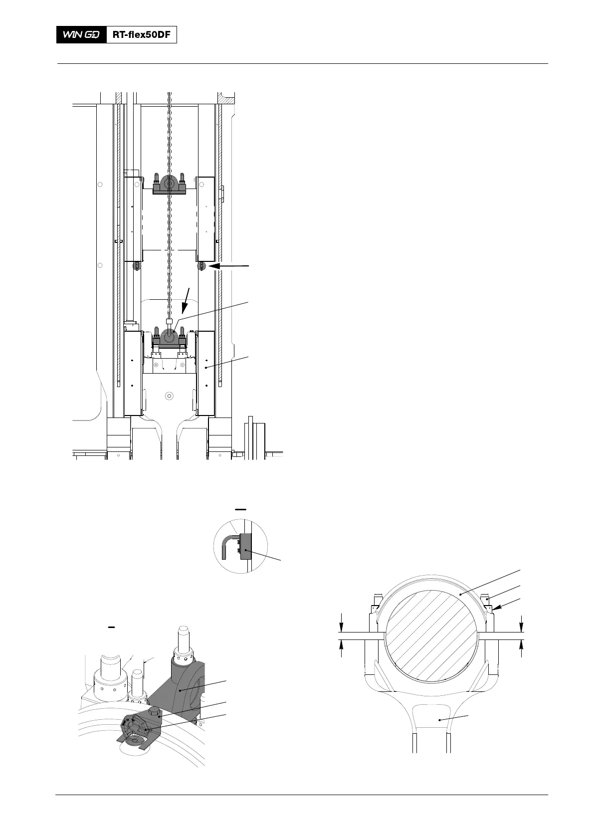
18) Operate the engine room crane to to lift
the guide shoes (1, Fig. 11) a small
distance.
19) Remove the four retaining
pins (94323).
Note: During step 20), make sure that the
elastic studs are aligned with the
holes in the crosshead pin.
20) Operate the engine room crane to
lower the guide shoes (3) on to the
elastic studs.
21) Remove the items that follow:
D The hook from the engine room
crane
D Retaining pins (94323)
D Stop plate (94370H)
D Eye bolts
D Lifting plate (94324).
22) Put the round nuts (3, Fig. 12) on the
elastic studs (2).
23) Tighten the round nuts (3) equally with
a round bar.
24) Measure the distance (X1, X2) between
the edges of the bearing shells (1) and
the connecting rod (4).
25) Refer to 0330−1, Group 0303 to get the
clearance values (X1, X2) for new
bearing shells.
26) Install the four round nuts (3) to the
connecting rod (4), refer to 9403−4.
2
4
3
1
013.629/05
Fig. 12
X1 X2
2016
Top End Bearing − Removal, Inspection and Installation
Fig. 11
94324
II
I
013.034/05
94323
II
94370H
94040−M8
94324
I
1