Maintenance3403−2/A1
Winterthur Gas & Diesel Ltd.
2/ 3
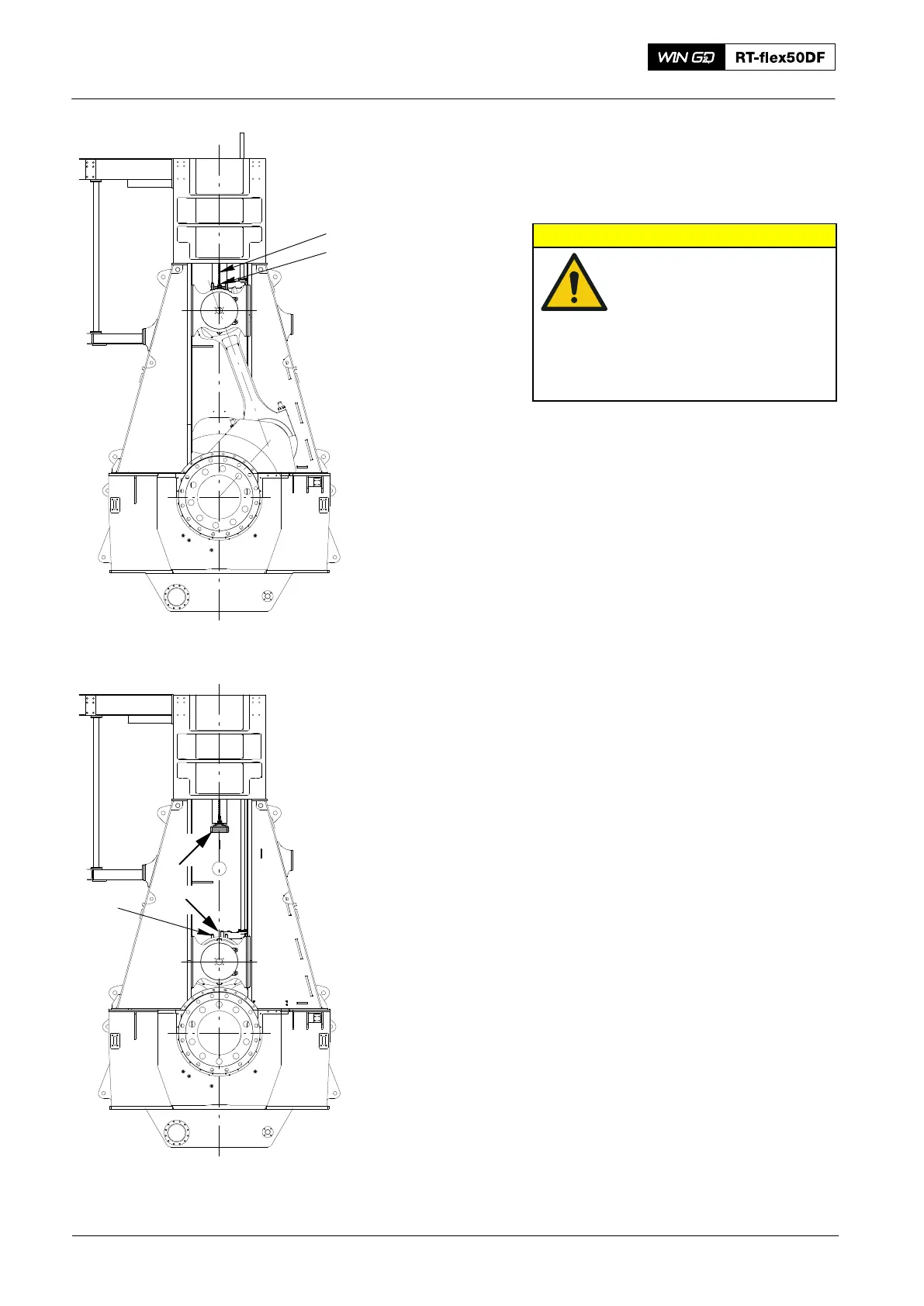
The crank may be turned max. 30_
towards T.D.C.
Pay attention to the warning plate provided
on the holders!
CAUTION
Carefully turn the crank
down until waisted studs 7
are out of piston rod foot 3
(Fig. ’3’).
Be careful, that the two
dowel pins 8 in crosshead
pin 4 do not jam in the pis-
ton rod foot.
8) Loosen and remove the screws
fastening compression shim 6.
9) Use the two eye bolts to remove the
compression shims 6.
For installation a new compression shim,
note that there are two different
compression shims, see below. Use an
applicable one for installation. Do the
installation in a reverse sequence to the
removal.
Note: Please note the correlation
between setting screw ’ST’ on
measuring gauge 94225 (see
2124−1) and the mean thickness of
built-in compression shims.
Piston: Changing the Compression Shims
2016
013.691/05
94333B
94333A
Fig. 2
013.692/05
7
I
II
Fig. 3