Maintenance
0330−1/A1
Winterthur Gas & Diesel Ltd.
7/ 25
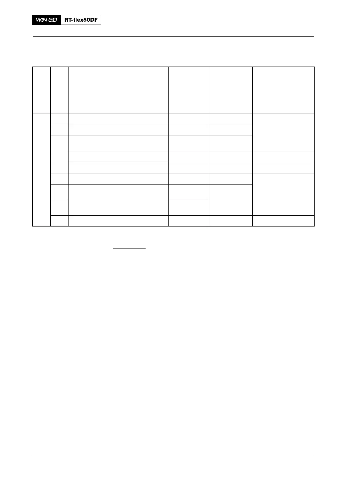
Crosshead Guide
Group
Key No.
Description Measured
Direction
Nominal
Dimension
(mm)
(usual, new)
Maximum Clearance,
Dimension
(mm)
(because of worn
components)
3326 Crosshead guide
1 Guide way (column) transverse 812
2 Guide shoe transverse
812
− 0.20
− 0.30
3 Guide shoe clearance 0.20−0.90 1.0
4 Guide rail, lateral clearance total 0.80−1.60 2.0
*5 Guide shoe, lateral clearance total 0.10−0.60
6 Guide shoe, bearing pin outer ∅
528
− 0
− 0.044
Guide shoe, bearing bore inner ∅
528
+ 0.101
0.044
7 Bearing clearance radial 0.064−0.145 0.25
To measure the clearances, refer to 3326−1.
* The clearance (3) is only correct with tie rods tightened.
* The clearance (5) refers to the space between the white metal of the guide
shoe and the connecting rod. The clearance 5 must be measured near the
holding plates which must rest on the crosshead pin at X.
2016
Clearance Table