Maintenance
8733−1/A1
Winterthur Gas & Diesel Ltd.
1/ 3
Removal, Grind, Install
Tools:
1 Grinding tool 94870 1 Grinding tool / countersunk screw M4 94870B
1 Screw-on sleeve 94870A 1 Locknut 94870C
1 Template 94870D 1 Hand drill
1. Preparation
1) Stop the engine (refer to the Operation
Manual 0310−1).
2) Set to off the fuel booster pump.
3) Make sure that there is no pressure in
the fuel rail.
4) Set to off the trace heating (if installed).
5) If necessary, remove the trace heating
cable.
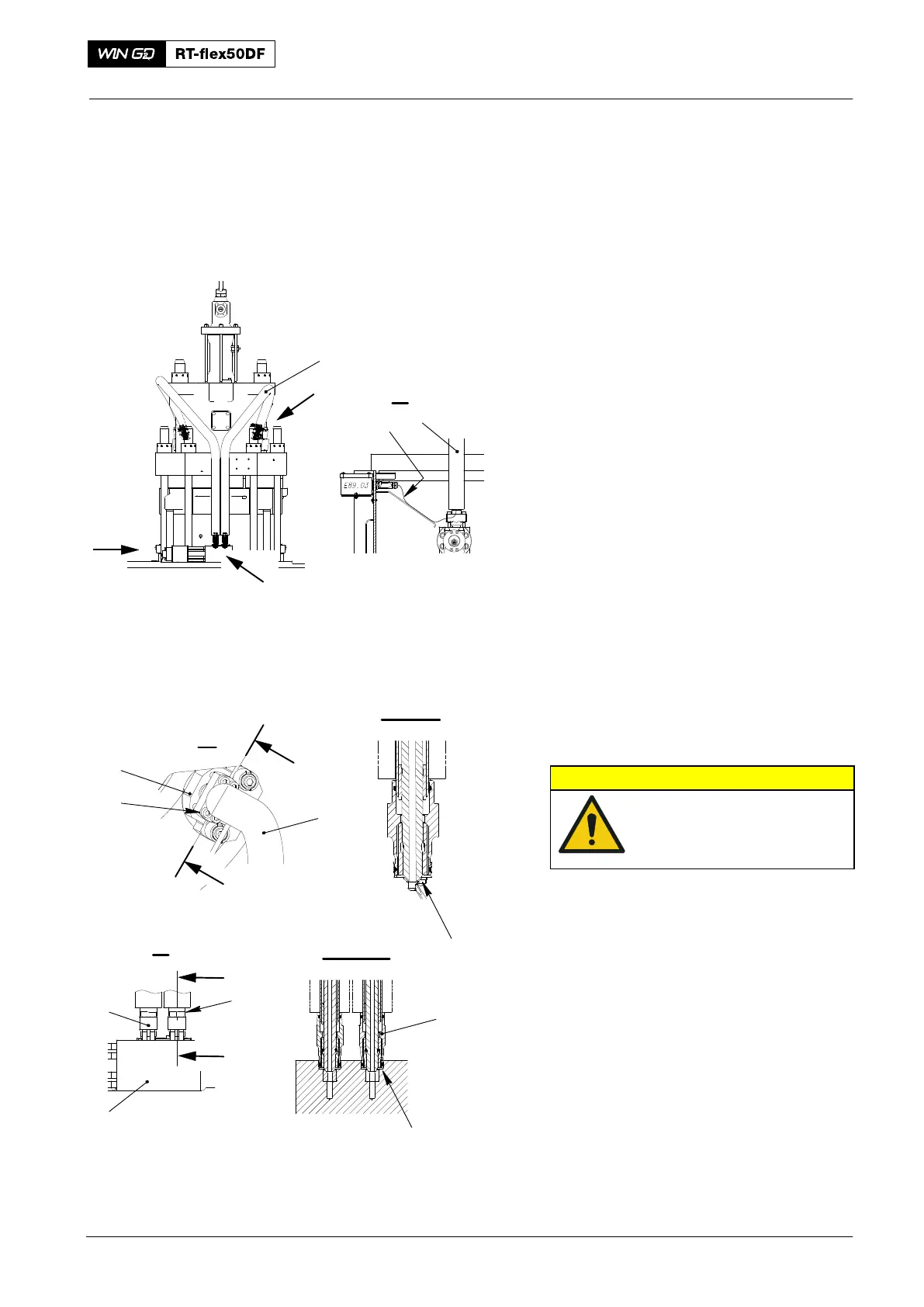
6) Disconnect the plug of trace heating
cable (2, Fig.1).
7) Remove the insulation from the
applicable HP injection pipe.
8) Put an oil tray under the applicable HP
injection pipe (1).
9) Carefully loosen the screws (5).
10) Lift the applicable flange (7) to drain the
fuel from the HP injection pipe (1).
2. Removal
CAUTION
Damage Hazard: Make sure
that you do not damage
the sealing faces or the HP
injection pipes.
1) On the injection valve (4), remove the
four screws (3).
2) On the flange (7) remove the four
screws (5).
3) Carefully remove the applicable HP
injection pipe (1) from the injection
valve (4) and the flow limiting valve (6).
4) Apply protection to the sealing faces
(SF) and the open ends of the HP
injection pipe (1).
2016
HP Injection Pipe
I
III
1
III
IV
IV
IV - IV
1
I
4
1
SF
SF
II
II
II - II
WCH02981
WCH02981
II
II
1
Fig. 1
2
3
4
5
6
7