03/2003
4-96
8850/ 510DP
REP 9.20
Repairs and Adjustments
REP 9.20 Image Module
Parts List on PL 9.9
NOTE: These are the instructions to install the Image Module Assembly Kit 600K58760. The
kit contains the following:
• Image Module Assembly
NOTE: In the following steps, the terms “Left” and “Right” describe machine locations as
observed from the Roll Media Supply Drawer side of the Printer.
WARNING
Switch off the Main Power Switch. Disconnect the Power Cord.
Removal
1. Remove the Developer Module (REP 9.5).
2. Remove the Developer Baffle (PL 9.8).
3. Remove the following:
a. Rear Door (PL 14.1)
b. Front Door (PL 14.3)
c. Right Side, Left Lower Cover (PL 14.3)
d. Right Side, Right Lower Cover (PL 14.3)
e. Right Side, Left Cover (three screws, two top, one bottom) (PL 14.3)
f. Right Side, Right Cover (three screws, one top, two bottom) (PL 14.3)
4. Remove the High Voltage Power Supply (REP 3.2).
NOTE: In the following steps, cut cable ties as necessary in order to remove the harness.
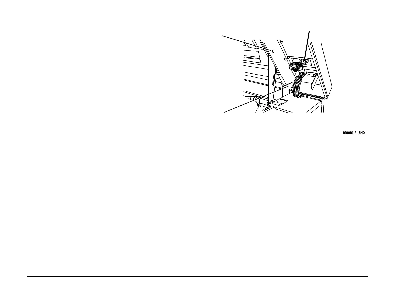
5. (Figure 1): (8850) Prepare to remove the Top Cover (Front).
(510dp)j Remove the Control Panel (REP XX.x
Figure 1 Preparing to Remove the Top Cover (Front)
Top Cover Pivot Pin
(will be removed in
Step 6)
2
Remove the Pin
2
Disconnect
A32/P1
 Loading...


