03/2003
4-97
8850/ 510DP
REP 9.20
Repairs and Adjustments
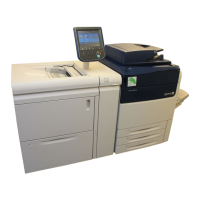
NOTE: (Figure 2): Observe the way that the Top Cover Pivot Pin engages the hole in the Inter-
lock Plate. This may be a difficult area during reassembly.
6. Close the Top Cover, open the Developer Module Cover, and remove the two pivot pins
shown in Figure 1 and Figure 2.
Figure 2 Top Cover Interlock Plate
7. Close the Developer Module Cover and lift off the Top Cover, being careful to disengage
the small pin from the Interlock Plate.
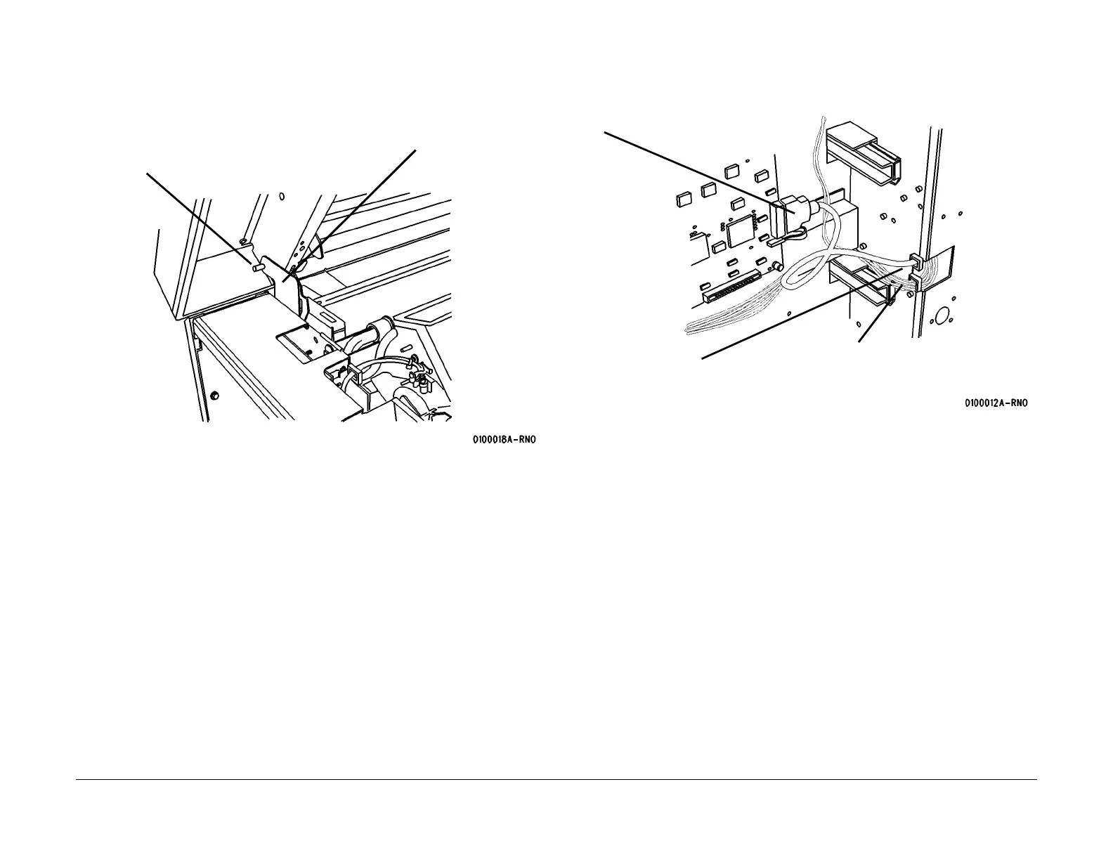
8. Open the Cutter Drawer.
9. (Figure 3): Disconnect the Video Cable Connector J608A from the Main PWB and push
the connector through the hole in the frame.
Figure 3 Disconnecting the video cable
interlock Plate
Top Cover Pivot Pin
1
Disconnect
J608A
3
Push the cable
through the hole
2
Remove the cable from
the clamps
 Loading...