03/2003
4-101
8850/ 510DP
REP 9.20
Repairs and Adjustments
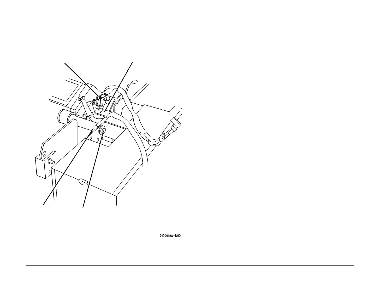
16. (Figure 10): Continue to pull the Video Cable through the hole after releasing it from the
cable guides.
Figure 10 Preparing to Remove the Image Module Assembly (View looking at the Rear
from the Right Side)
17. Lift out the Image Module Assembly / Pivot Bar combination.
Replacement
1. Reverse the removal steps for replacement of the Image Module Assembly.
2. Enter the diagnostics [0903] and input the LED rating designated on the new image mod-
ule, then press Enter.
3. Perform Electrostatic Series (ADJ 9.2).
2
Unfasten the Video
Cable
1
Disconnect the con-
nectors and remove
the Charge Scorotron
Harness
4
Remove the
spacer
3
Remove the bolt
 Loading...