03/2003
2-5
8850/ 510DP
J1-01 Undertoned Fault RAP
Status Indicator RAPs
YN
Go to BSD 4.3, Drum Drive, to repair the drive circuit.
The J1-01 code is displayed as the prints are being made.
YN
Complete the Service Call.
Use the last print to check the image density. The image density of the 1.0 Solid Square in
the center of the Test Pattern [0955-5] is equal to or less than the 1.20 Density Square on
the Output Reference SIR 495.1.
YN
Perform the Tone-Up procedure [09-06]. If the printer does not tone up, perform the
Image Density Adjustment. Go to ADJ 9.3
NOTE: : If unable to perform ADJ 9.3, replace the Developer and perform GP-8 Toner
Control System Calibration Procedure.
Enter the code [9-21-4]in order to switch on the Main Drive Motor and the Toner Sensor circuit.
Connect the (+) meter lead to the Main PWB A3J606-14 and the (-) meter lead to A3J606-13.
There is between +5.2 and +6.0 VDC present.
YN
Connect the (+) meter lead to the Toner Sensor A22Q1P1-1 and the (-) meter lead to
ground. There is less than +10 VDC present.
YN
Disconnect Toner Sensor A22Q1P1 from A22Q1J1. Connect the (+) meter lead to
the Main PWB A3J606-16 and the (-) meter lead to ground. There is less than
+10.0 VDC present.
YN
Replace the Main PWB, A3, PL 1.1.
Check for an open or short circuit to ground in the wires connected to A22Q1P1-3
(ORN) and A22Q1P1-4 (YEL). If the wires are OK, replace the Toner Sensor,
A22Q1, PL 9.7.Then perform GP 8 Toner Control System Calibration Procedure.
Check for an open or short circuit to ground in the wire connected to the A22Q1P1-3
(ORN). If the wire is OK, replace the Toner Sensor.
Replace the Main PWB, A3, PL 1.1. If the problem persists, enter the code [0926] to reset the
NVM.
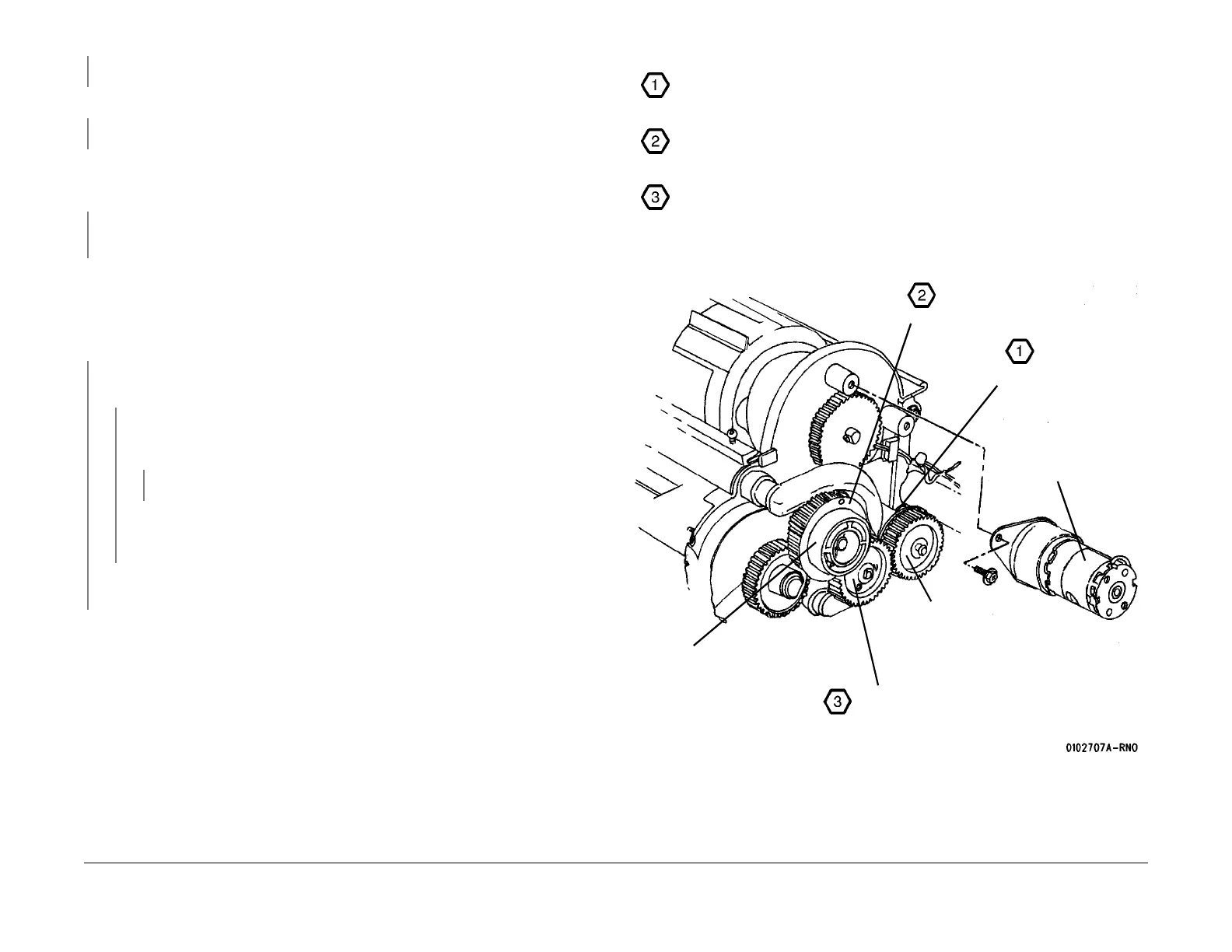
Figure 2 Developer Housing and Auger Drive Gears
Ensure that the Rear Auger Drive Gear is positioned with the flange as shown.
Ensure that the Developer Housing Drive Gear is positioned with the flange as
shown.
Ensure that the Front Auger Drive Gear is captured in position by the Rear Auger
Drive Gear Flange and the Developer Housing Drive Gear flange.
Developer
Housing Drive
Gear
Flange
Flange
Cartridge Drive
Motor removed
for clarity
Rear Auger
Drive Gear
Front Auger Drive Gear
 Loading...


