03/2003
2-14
8850/ 510DP
1.1 AC Power RAP
Status Indicator RAPs
1.1 AC Power RAP
This RAP is used for problems in the AC circuitry for primary distribution and control. The Con-
trol Panel may be illuminated, but the copier will not begin to initialize.
The problem may occur in the Filtered AC Receptacle, Main Power Switch, Ground Fault Pro-
tector, Surge Voltage Protector, a shorted Varistor, Noise Filter, or the Main PWB. In which
case the AC Module Assembly (A1) will have to be replaced. The AC Module should not be
opened to replace these items. If opened, the EMI protection will be compromised and may
result in electrical noise problems within the Printer or in the Customer’s site.
NOTE: Refer to BSD 1.1 Main Power on (50 and 60 Hz) located in Section 7 of this manual as
you go through this procedure.
Initial Actions
• Check that the correct voltage is being applied to the printer from the wall outlet.
• Check that the Ground Fault Protection Device is not activated. If activated, switch off the
Printer and reset the Ground Fault Protector. Switch on the Printer, if the Ground Fault
Protector activates go to the 1.3 Ground Fault RAP.
Procedure
WARNING
High Voltage. Use extreme caution when working near the AC Module. Do not discon-
nect any plugs or wires while the Power Cord is plugged into the wall outlet and the
Main Power Switch is switched on.
The Controller external LEDs are on.
YN
There is ACH Voltage between Pin 1 and Pin 3 of connector A1P5.
YN
Replace the AC Module Assembly (A1) (PL 1.1).
Check the harness between the AC Module and the Controller for an open or short circuit.
If the harness is okay, refer to the AccXES Controller service manual to troubleshoot the
AC voltage.
There is ACH voltage between Pin 1 and Pin 3 of connector A1P5.
YN
Replace the AC Module Assembly (A1) (PL 1.1).
There is ACH voltage between Pin 1 and Pin 3 and Pin 6 and Pin 8 of connector A1P3.
YN
Replace the AC Module Assembly (A1) (PL 1.1).
Check the harnesses between the AC Module Assembly (A1) and the Low Voltage Power Sup-
plies for an open or short circuit. If okay, go to the 1.2 DC Power RAP.
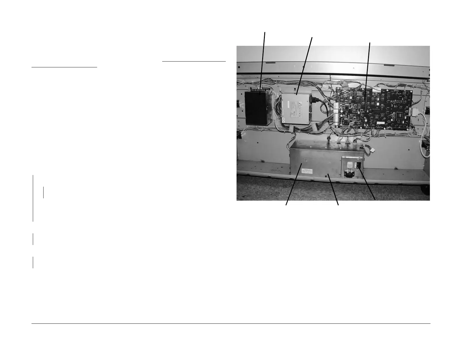
Figure 1 Input Power Components
LVPSPS2 LVPSPS1
Main
PWB (A3)
AC Module Ground Fault
Protector
Main Power
Switch
 Loading...


