03/2003
2-15
8850/ 510DP
1.2 DC Power RAP,
Status Indicator RAPs
1.2 DC Power RAP
This RAP is used to locate problems in the DC power generation and distribution circuitry.
The LEDs on the Main PWB (A3), when lit, indicate that the DC voltages are available on the
Main PWB (A3). Refer to BSD 1.2 DC Power Generation when performing this procedure.
Initial Actions
• Check that connector A3P/J618 is fully seated.
• Ensure that ACH and ACN are present at A5P/J1 on the Low Voltage Power Supply
(A5PS1).
Procedure
The +3.3V (CR 11), +12V (CR 12), +5V (CR 4) LEDs, and 5VSB (CR3) on the Main PWB
are lit.
YN
Check the wires between the Low Voltage Power Supply (A5PS1) for a short to the frame.
If there is no short, replace the Low Voltage Power Supply (A5PS1) PL 1.1.
Connect the negative (-) meter lead to the machine frame and measure the following voltages.
A voltage is out of specification.
YN
Replace the Main PWB (A3) PL 1.1.
Replace the Low Voltage Power Supply ( A5PS1) PL 1.1.
1.3 Ground Fault Protector RAP
This RAP is used to locate and repair ground fault problems in the primary AC power distribu-
tion circuitry. You may have been directed to this RAP from another AC Power RAP that traced
the loss of AC power to the GFP device.
The 8850/510dp Printer is equipped with a Ground Fault Protector (GFP) device that detects
excessive current leakage to ground. If excessive leakage is detected, the device will remove
all power to the printer. In addition, there is a varistor connected across the output side of the
Ground Fault Protector to suppress electrical noise in order to meet EMI standards. If the
Varistor fails in a shorted mode it will cause the GFP to continually activate.
Procedure
WARNING
High Voltage. Use extreme caution when working near the AC Module. Do not discon-
nect any plugs or wires while the Power Cord is plugged into the wall outlet and the
Main Power Switch is switched on.
• Check that the correct voltage is being applied to the Printer from the wall outlet.
• Test the Ground Fault Protector (GFP). With the Power Cord plugged into the Wall outlet,
and the Main Power Switch switched on; press the TEST button using a pointed tool. The
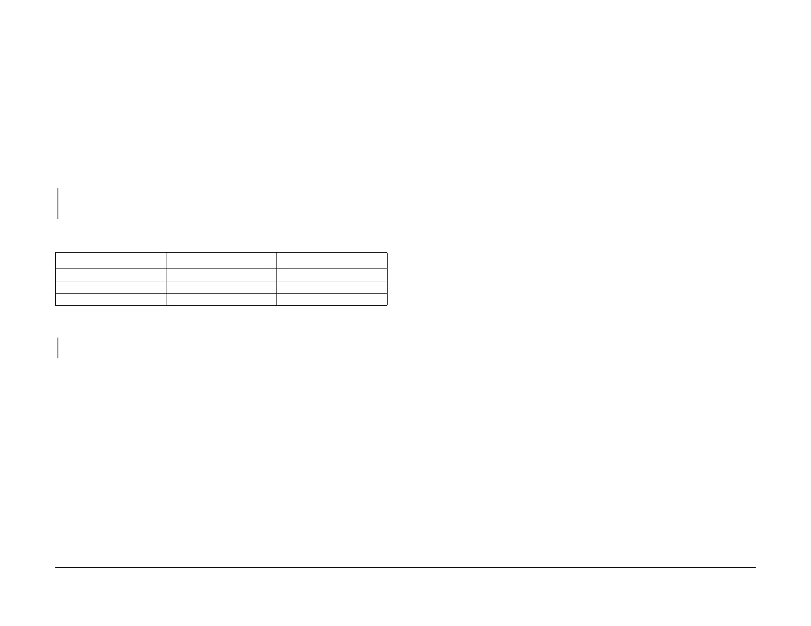
GFP should switch to the off position. If not, replace the AC Module Assembly (PL 1.1).Table 1 Voltage Checks
PIN (+) Voltage Tolerance
A3P618-1 +3.3 VDC +\- 5%
A3P618-4, and 9 +5 VDC +\- 5%
A3P618-10 +12 VDC +\- 5%
 Loading...